Continue to Site

Welcome to EDAboard.com

Welcome to our site! EDAboard.com is an international Electronics Discussion Forum focused on EDA software, circuits, schematics, books, theory, papers, asic, pld, 8051, DSP, Network, RF, Analog Design, PCB, Service Manuals... and a whole lot more! To participate you need to register. Registration is free. Click here to register now.

How to test this GTO " FG1000BV-90DA " ? thanx

Status
Not open for further replies.

dineshdeshmuk

Full Member level 5
Joined
Sep 12, 2011
Messages
285
Helped
18
Reputation
36
Reaction score
18
Trophy points
1,298
Activity points
3,131
How to test this GTO " FG1000BV-90DA " ?

**broken link removed**

Why not the manufacturer's do usually use GTOs in place of IGBT Modules ?

thanks a lot
 

MITSUBISHI GATE TURN-OFF THYRISTORS
FG1000BV-90DA
https://www.mitsubishielectric.com/...er/thyristors/gto/gto_lv4/fg1000bv-90da_e.pdf

Device principle description

Normal thyristors (Silicon-controlled rectifier) are not fully controllable switches (a "fully controllable switch" can be turned on and off at will).
Thyristors can only be turned ON and cannot be turned OFF. Thyristors are switched ON by a gate signal, but even after the gate signal is
de-asserted (removed), the thyristor remains in the ON-state until any turn-off condition occurs (which can be the application of a reverse
voltage to the terminals, or when the current flowing through (forward current) falls below a certain threshold value known as the "holding current").
Thus, a thyristor behaves like a normal semiconductor diode after it is turned on or "fired".

The GTO can be turned-on by a gate signal, and can also be turned-off by a gate signal of negative polarity.

Turn on is accomplished by a "positive current" pulse between the gate and cathode terminals. As the gate-cathode behaves like PN junction,
there will be some relatively small voltage between the terminals. The turn on phenomenon in GTO is however, not as reliable as an SCR (thyristor)
and small positive gate current must be maintained even after turn on to improve reliability.

Turn off is accomplished by a "negative voltage" pulse between the gate and cathode terminals. Some of the forward current (about one-third
to one-fifth) is "stolen" and used to induce a cathode-gate voltage which in turn induces the forward current to fall and the GTO will switch off
(transitioning to the 'blocking' state.)

GTO thyristors suffer from long switch off times, whereby after the forward current falls, there is a long tail time where residual current
continues to flow until all remaining charge from the device is taken away. This restricts the maximum switching frequency to approx 1 kHz.
It may however be noted that the turn off time of a comparable SCR is ten times that of a GTO. Thus switching frequency
of GTO is faster than an SCR.

quotation: Gate turn-off thyristor From Wikipedia

FEATURE AND APPLICATION OF GATE TURN-OFF THYRISTORS
https://www.mitsubishielectric.com/semiconductors/files/manuals/gtothyristors.pdf

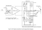
Typical GTO Thyristor Driver Circuit
GTO Thyristor_Drive_circ_01.jpg

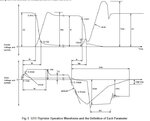
GTO Thyristor Definition of Parameters
GTO Thyristor_Op&Param_01.jpg

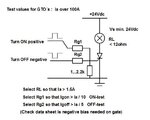
GTO Thyristor over 100Amp Test Circuit
GTO Thyristor_Test_circ_01.jpg
 
thanks a lot but

Why not the manufacturer's do usually use GTOs in place of IGBT Modules ?

And, what does it mean by " check data sheet is negative bias needed on gate " ?

thanks a lot
 
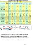
Why not the manufacturer's do usually use GTOs in place of IGBT Modules ?

Here is some comparisons..........
Drive_Pow_Devi_Compar_01.jpg

what does it mean by " check data sheet is negative bias needed on gate " ?

Some very noisy circuits with high transients may GTO need few volts negative low ohmic supply for blocking after OFF-pulse.
Not needed in test.
 
Here is some comparisons..........
View attachment 62717


Some very noisy circuits with high transients may GTO need few volts negative low ohmic supply for blocking after OFF-pulse.
Not needed in test.

When considering Power GTO is best as compared to IGBT
And When considering Switching times GTO is worst as compared to IGBT

Am i right ?

What does it mean when you saying that " SCGT, IGCT Vs. IGBT, IEGT " ?
do you mean that conduction losses for all these devices of the same volt - amps capacities same ?

thanks btw
 
Reply needed from you KAK111, as asked by Munzir ..... I also want you to confirm what he has mentioned above ?
 

I would not say which one is best or worst but........
Generally today, when talking about high power systems...
GTO can handle bigger power (several MegaWatts) / IGBT under 1 MW
GTO can handle higher current 10kA... / IGBT current 2-4kA
in PWM systems GTO is quite slow 1...2kHz / IGBT 100...200kHz
GTO effiency is much lower , when used in PWM
GTO control circuit is much more complicated and must be able to handle big currents ( Igate off current can be over 1kA pulse)
IGBT current gain is very high

Modern circuits under 100kW usually do not use GTO`s.

What does it mean when you saying that " SCGT, IGCT Vs. IGBT, IEGT " ?
Symmetrical Gate Commutated Thyristor (SGCT)
Integrated Gate-Commutated Thyristor (IGCT)
Insulated-gate bipolar transistor (IGBT)
Injection enhancement gate transistor (IEGT)
more you find with google..........

do you mean that conduction losses for all these devices of the same volt - amps capacities same ?
I mean very big differencies in losses are not found between components in same class of volt - amps capacity
 
MITSUBISHI GATE TURN-OFF THYRISTORS
FG1000BV-90DA
https://www.mitsubishielectric.com/...er/thyristors/gto/gto_lv4/fg1000bv-90da_e.pdf

Device principle description

Normal thyristors (Silicon-controlled rectifier) are not fully controllable switches (a "fully controllable switch" can be turned on and off at will).
Thyristors can only be turned ON and cannot be turned OFF. Thyristors are switched ON by a gate signal, but even after the gate signal is
de-asserted (removed), the thyristor remains in the ON-state until any turn-off condition occurs (which can be the application of a reverse
voltage to the terminals, or when the current flowing through (forward current) falls below a certain threshold value known as the "holding current").
Thus, a thyristor behaves like a normal semiconductor diode after it is turned on or "fired".

The GTO can be turned-on by a gate signal, and can also be turned-off by a gate signal of negative polarity.

Turn on is accomplished by a "positive current" pulse between the gate and cathode terminals. As the gate-cathode behaves like PN junction,
there will be some relatively small voltage between the terminals. The turn on phenomenon in GTO is however, not as reliable as an SCR (thyristor)
and small positive gate current must be maintained even after turn on to improve reliability.

Turn off is accomplished by a "negative voltage" pulse between the gate and cathode terminals. Some of the forward current (about one-third
to one-fifth) is "stolen" and used to induce a cathode-gate voltage which in turn induces the forward current to fall and the GTO will switch off
(transitioning to the 'blocking' state.)

GTO thyristors suffer from long switch off times, whereby after the forward current falls, there is a long tail time where residual current
continues to flow until all remaining charge from the device is taken away. This restricts the maximum switching frequency to approx 1 kHz.
It may however be noted that the turn off time of a comparable SCR is ten times that of a GTO. Thus switching frequency
of GTO is faster than an SCR.

quotation: Gate turn-off thyristor From Wikipedia

FEATURE AND APPLICATION OF GATE TURN-OFF THYRISTORS
https://www.mitsubishielectric.com/semiconductors/files/manuals/gtothyristors.pdf

Typical GTO Thyristor Driver Circuit
View attachment 62680

GTO Thyristor Definition of Parameters
View attachment 62681

GTO Thyristor over 100Amp Test Circuit
View attachment 62682

Kindly, take any GTO as a example and show me how to calculate the values of RL, Rg1 & Rg2 , urgently required ... plz help

thanks
 
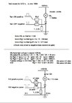
take any GTO as a example and show me how to calculate the values of RL, Rg1 & Rg2 ,

Like this........
GTO_test_circ_01math.jpg
 
what RL exactly is ? Is it a lamp or can i used any resistor ?

RL is not so exact value , it is only used to cause sufficient anode current during test.

Any resistive load can be used . (lamp or resistor)
 
Status
Not open for further replies.

Similar threads

Part and Inventory Search

Welcome to EDABoard.com

Sponsor

Back
Top