Continue to Site

Welcome to EDAboard.com

Welcome to our site! EDAboard.com is an international Electronics Discussion Forum focused on EDA software, circuits, schematics, books, theory, papers, asic, pld, 8051, DSP, Network, RF, Analog Design, PCB, Service Manuals... and a whole lot more! To participate you need to register. Registration is free. Click here to register now.

pic18f4550 (configuration)

Status
Not open for further replies.

khiat

Member level 1
Joined
Feb 5, 2011
Messages
40
Helped
0
Reputation
0
Reaction score
0
Trophy points
1,286
Activity points
1,568
hello ,
please i need your help ,
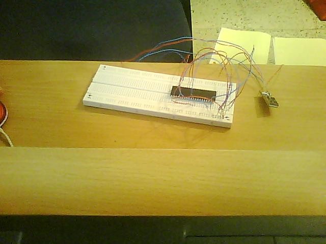
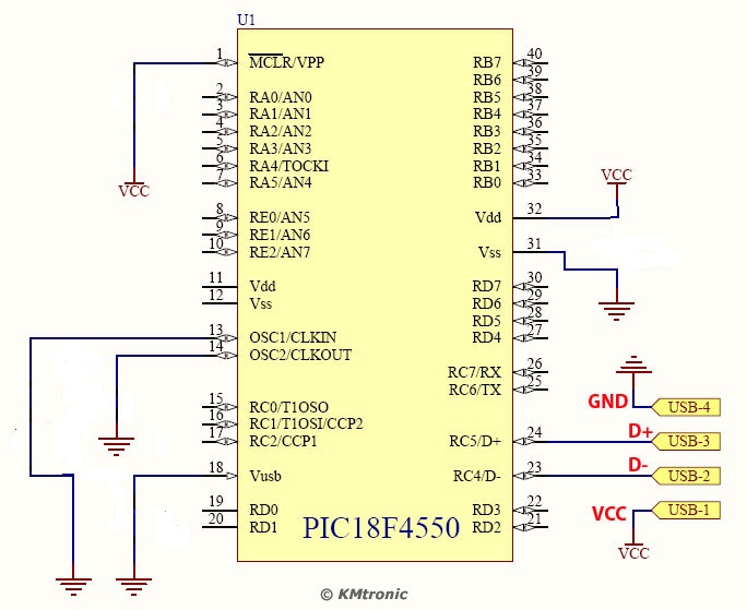
I want realized my project, I implemented all exactly as shown in the schimatic
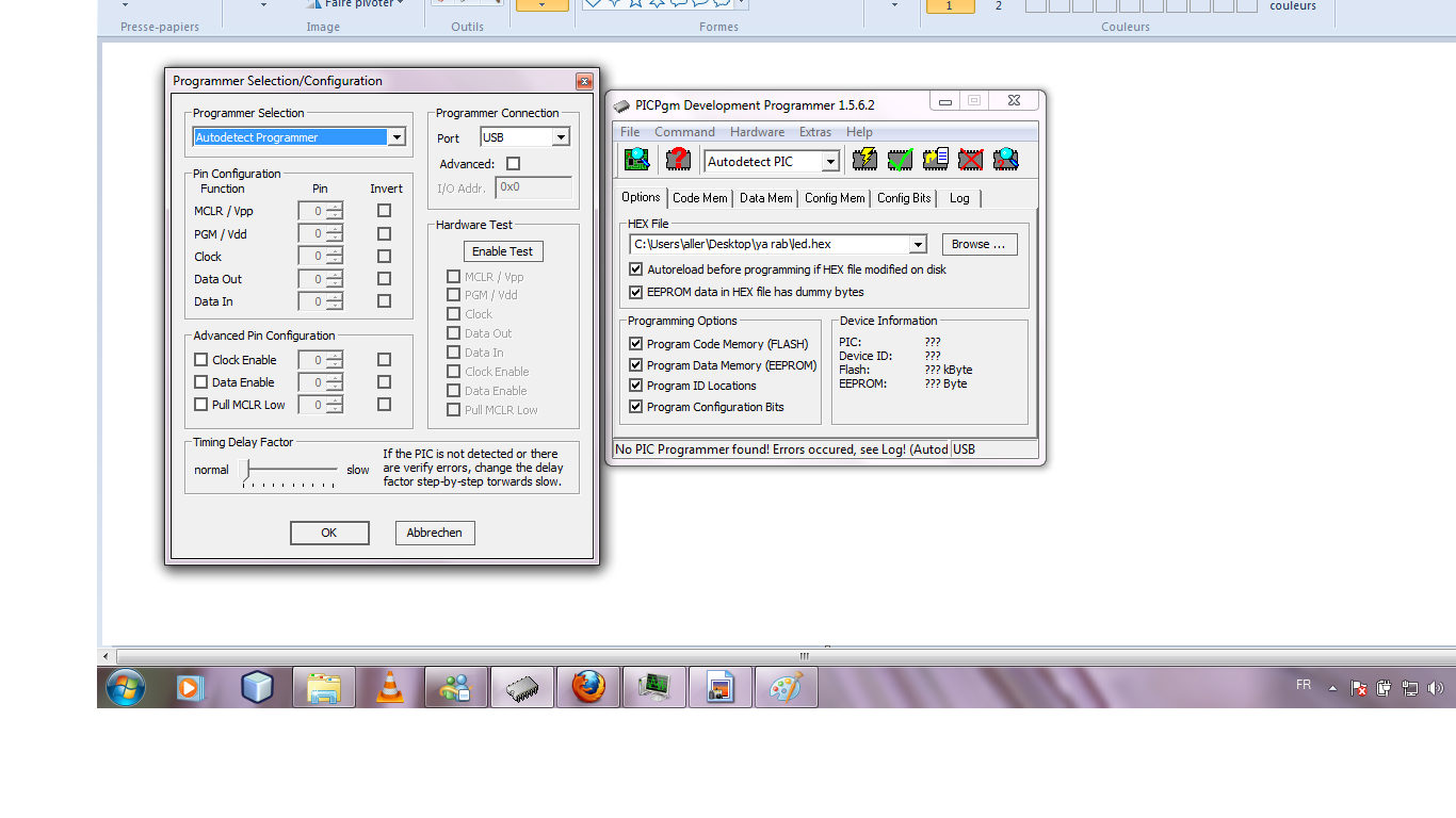
and I use PICPgm as software for programming my pic18f4550
but the software does not detect any pic connected
(I have for other project that uses the 20MHz crystal etc.,
but I do not think its because of that the software does not detect my pic).
if you can please tell me where is the problem and how I connected to my laptop
(configuration) , thank you

.
 

2. What you need

To use PICPgm, you need the following environment:

PC running Windows (Linux is also supported but not covered in this HowTo)
PICPgm Software installed on your PC (download here)
PIC programmer hardware (list of supported programmers)
Parallel port (LPT), serial port (COM) or USB port (only supported USB programmer so far is PICPgm USB programmer)

**broken link removed**

https://www.edaboard.com/threads/42418/

PIC18F2XXX/4XXX FAMILY
Flash Microcontroller Programming Specification
**broken link removed**
 
Last edited:

i have windows and i have install PICPgm,but i have this message " no piC found" please help me , there is no probleme in my
sChematiC
 

PICPgm is a PC-Software to program PIC microcontrollers using an external programmer hardware connected to the PC.
ie you need programmer circuit between PC and PIC-ic

read these ..............
Programmer Hardware
**broken link removed**

PICPgm Quick Start Guide
**broken link removed**

and for programming connections are...........

read 2.0 PROGRAMMING OVERVIEW
**broken link removed**

Looking at the 18F4550 datasheet, the corresponding pins are:

Vpp (1)
Vdd (11)
Vss (12)
PGD (40)
PGC (39)

The 18F4550 supports low-voltage programming (using 5V instead of ~11V).
To use LVP, the PGM (38) pin needs to be set high. If LVP is disabled, it functions as an I/O pin.
(Side note: An HVP programmer must be used to enable LVP on a new PIC. Also, with LVP enabled,
PGM (38) no longer functions as an I/O pin.)

The 5V/GND connections on the 18F4550 should be made as follows:

5V (11)
5V (32)
GND (12)
GND (31)

Notice that there are 2 connections for Vdd (5V) and Vss (GND). All four must be made.

Check that programmer can power the chip via these pins,
however it is better to use your own power source, connecting both a 5V signal
 
Last edited:

thank you ,I implemented all exactly as shown in my schimatic .
now a connect my project to laptop via cable usb
and i open PICPgm and i have "no pic found"

please i hepl and thank you
 

1. You need external programmer between PIC and PC (look previous post)
2. Connections are shown in my previous post
3. You must program Microchip provided free firmware for USB HID
to make USB pins usable in PIC
Using the Microchip bootloader you can program your code and change your firmware vie
USB without the need for programmer!

read..........
PIC-USB-4550 development board
Users Manual
https://www.olimex.com/dev/pdf/PIC/PIC-USB-4550.pdf
 

thank you very much ,

1)for your first aswere "1. You need external programmer between PIC and PC (look previous post)" ,you do not have a link(url) to understand or download or even buy it
but if you want to follow wonderful project of Kuzito,we do not need external programmer https://www.edaboard.com/threads/126795/

2)for your second answer, you can please if not too much to correct my schematic


3)for your third answer, please I need a link(url) to download

and thank you for your reply realy, thank you ,thank you very much
 

The best answer IMO would be "Get a Pickit 2". You can buy fully cumpatible clones of those on ebay for few dollars with free worldwide shipping.

Once upon a time i tried to construct my own programmer (quite a few of them actually) and ended with not even one working right + one damaged uC. After summing up costs of parts and burnt MCU it turns out i could've bought an original PK2 from Microchip for that money.

The price of PK2 (or PK3 if you have a bit more money and want to be able to use new MCHP products) is very, very competitive given that u get a full featured programmer and debugger operational directly from MPLAB IDE without third party downloading software
 

thank you , but i want to follow wonderful project of Kuzito,we do not need external programmer My experiments with PIC18F4550 <> USB
 

Sorry about bad links , fixed and working now.

1 .Programmer Hardware
Programmer Overview

PICPgm supports all kind of serial port programmers as well as parallel port programmers.
The most popular PIC programmers (e.g. JDM, Tait, Microchip AN589 programmer, ...)
are pre-configured and will be automatically detected by the software. In the table below,
you will find a list of all nativly supported programmers.
look.............
**broken link removed**

2. Connections
18f4550 prog_pin_01.jpg 18f4550 prog_pin_02.jpg

Looking at the 18F4550 datasheet, the corresponding pins are:

Vpp (1)
Vdd (11)
Vss (12)
PGD (40)
PGC (39)
The 5V/GND connections on the 18F4550 should be made as follows:
5V (11)
5V (32)
GND (12)
GND (31)

3.
Microchip Free USB Software
**broken link removed**

USB Bootloader
**broken link removed**

4. Training & Support Home Page
**broken link removed**

4.1. PIC18F2455/2550/4455/4550 Data Sheet
https://ww1.microchip.com/downloads/en/DeviceDoc/39632e.pdf

PIC18F4550 More docs
PIC18F4550

USB related.......
**broken link removed**

Burning in the bootloader
1 Burning in the bootloader

PIC18F4550 Instruction Set Reference Manual
https://ww1.microchip.com/downloads/en/DeviceDoc/31029a.pdf

PIC18F4550 Technical Library (Includes Application Notes, etc)
**broken link removed**

How to build a USB device with PIC 18F4550 or 18F2550
How to build a USB device with PIC 18F4550 or 18F2550 (and the ...


5. Think about something like this............
PICkit 2 Development Programmer/Debugger..... about 50$
**broken link removed**
 
Last edited:
  • Like
Reactions: khiat

    khiat

    Points: 2
    Helpful Answer Positive Rating
thank you ,always the problem PICPgm does not detect anything and I begin to lose hope to succeed to program my pic, I buy a near all the necessary equipment (Breadboard, pic18f455, LED, USB connector), I followed the connections like you mount it in your picture, and for some software I could not download ,but thank you for your hepl and reply
 

What kind of programming device you have between PIC and PC.

PICPgm supports all kind of serial port programmers as well as parallel port programmers.
The most popular PIC programmers (e.g. JDM, Tait, Microchip AN589 programmer, ...)
are pre-configured and will be automatically detected by the software.
 

thank you, nothing, laptop usb cable directly to pic

---------- Post added at 21:35 ---------- Previous post was at 21:28 ----------


usb cable to pic and laptop like scématic ,i want realized porject like " My experiments with PIC18F4550 <> USB " thank you
 

So I started to think

My posts..........
Yesterday 23:52 #2 , Today 11:58 #4 and Today 18:43 #10
Programmer Hardware
 
Last edited:

I did not understand your last message, sorry for your precious time really sorry but if you can help me,i can't connect directly pic to my laptop via usb cable ,thank you
 

Khiat, please read the previous posts carefully. You CAN NOT program a blank 18F4550 through the USB pins. You MUST use a programmer connected to the PGD/PGC/PGM/VPP pins.

The reason your USB link does not work is there is no code inside the PIC to respond to the PC data, it arrives at the pins but goes no further.

AFTER you have programmed the PIC as described, it is possible to use a bootloader program to transfer data and programs from the PC to the PIC. You have to start the process by installing a bootloader and that will only work if you use a programming device. As suggested, The PicKit programmers are very good value for money, program all PIC types and have debugging facilities in them as well.

Brian.
 
  • Like
Reactions: khiat

    khiat

    Points: 2
    Helpful Answer Positive Rating
thank you very much

---------- Post added 02-10-11 at 00:11 ---------- Previous post was 01-10-11 at 22:55 ----------

thank you
1)but ,how Kuzito do for his project "My experiments with PIC18F4550 <> USB",his does not use a programming device.
2)after i use a programming device and when the PIC does not become a virgin I can program it without using a programming device .or a programming device is necessary.
3)the problem arises when the pic,in rpoject de Kuzito the pins PGD/PGC/PGM is not conneted
please i want understand how Kuzito do.
I saw in another site that connects the PC directly to the peak as "hello word"

thank you

---------- Post added at 01:49 ---------- Previous post was at 00:11 ----------

if it is not too much to ask can you please answer me to my quetions
i sorry , i have many questions
1)is it a problem when the pic is blank
2)supposing that my pic is not blank and I want to connect my pic directly to my PC via USB without using a programming device and the pins are not PGD/PGC/PGM connected
then the software PICPgm detects my pic (how and why),if not then why the project of kuzito work. if yes then why
3)if we return to the project of kuzito, how the pc detects his hardware without using a programming device
4)PICPgm is a bootloader
thank you
 

Ok, when u purchase an MCU it is blank. Which means it simply won;t work in any way, it's a brick of silicon. For the MCU to be able to communicate with PC by USB you need to tell the MCU how. This is called BOOTLOADER. Bootloaders enable you to download program into MCU using various communication interfaces (most common are UART and USB). Thas is what you are writing about. The bad thing about bootloader is that it needs to be downloaded into MCU the ordinary way, which is using a programmer.

YOU CANNOT PROGRAM BLANK MCU WITH USB!

On the other hand on your photo I can't see a crystal oscillator. I don't think that USB would even work without one, it needs a somewhat precise frequency reference which is normally provided by crystal oscillator fed into PLL for frequency multiplication

If someone who you know has programmer like Pickit then ask them to program bootloader into MCU for you. I think you can also buy MCU preprogrammed with bootloader on ebay. There are some microcontrollers which have a built in bootloader, but i don;t think that Microchip produces those. I know that some Cypress chips hava that feature. Also (but I'm not sure) some ColdFire and ARM core microcontrollers also have this feature.
 
  • Like
Reactions: khiat

    khiat

    Points: 2
    Helpful Answer Positive Rating
Well your pic is never going to work on its own.
There is no oscillator and Vusb doesnt have a capacitor to ground !
 

thank you , very muCh realy

please can you give me the frequencies of "Programmer PICKIT 2" I need to avoid any problems and also I need for cable (RS232 and USB)

thank you

---------- Post added at 23:58 ---------- Previous post was at 23:56 ----------

thank everyone
 

Status
Not open for further replies.

Similar threads

Part and Inventory Search

Welcome to EDABoard.com

Sponsor

Back
Top