Continue to Site
Follow along with the video below to see how to install our site as a web app on your home screen.
Note: This feature may not be available in some browsers.
movlw   b’00101000’ ; setup value
                       ;   into W register
banksel SSPCON1     ; select SFR
                    ;   bank
movwf   SSPCON1     ; configure for
                    ;   Master I
2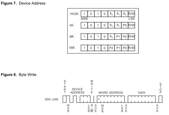
CThe device address word consists of a mandatory one, zero sequence for the first four most significant bits as shown. This is common to all the EEPROM devices. The next 3 bits are the A2, A1 and A0 device address bits for the 1K/2K EEPROM. These 3 bits must compare to their corresponding hard-wired input pins.
................................
The eighth bit of the device address is the read/write operation select bit. A read operation is initiated if this bit is high and a write operation is initiated if this bit is low. Upon a compare of the device address, the EEPROM will output a zero. If a compare is not made, the chip will return to a standby state.
Dear all
Let say we joint same kind of slave to the bus ( two IC 2402 )
Embedded_Geek said:2^3 = 16

Dear all
what is the advantage of 10bits address mode over 7bit address mode
A restart condition indicates that a device would like to transmit more data, but does not wish to release the line. This is done when a start must be sent, but a stop has not occurred. It is also a convenient way to send a stop followed by a start right after each other. It prevents other devices from grabbing the bus between transfers. If you are talking to one device, such as a serial EEPROM, you may not want to be interrupted when transmitting addresses and gathering data. A restart condition will handle this.
The purpose of is to allow combined write/read operations to one or more devices without releasing the bus and thus with the guarantee that the operation is not interrupted.
This seems like a confusing term at first as you ask yourself why bother with it as it is functionally identical to the sequence :
S ADDR (R/W) DATA A P
The only difference is that for a repeated start you can repeat the sequence starting from the stop bit (replacing the stop bit with another start bit).
S ADDR (R/W) DATA A Sr ADDR (R/W) DATA A P
and you can do this indefinitely.
Note: Reception of both S or Sr force any I2C device reset its internal bus logic so sending S or Sr is really resetting all the bus devices. This can be done at any time - it is a forced reset.
The main reason that the Sr bit exists is in a multi master configuration where the current bus master does not want to release its mastership. Using the repeated start keeps the bus busy so that no other master can grab the bus. Because of this when used in a Single master configuration it is just a curiosity.