Continue to Site

Welcome to EDAboard.com

Welcome to our site! EDAboard.com is an international Electronics Discussion Forum focused on EDA software, circuits, schematics, books, theory, papers, asic, pld, 8051, DSP, Network, RF, Analog Design, PCB, Service Manuals... and a whole lot more! To participate you need to register. Registration is free. Click here to register now.

[SOLVED] PIC complete discussion for all

Status
Not open for further replies.
this is very generic to pic16 but concept is almost same...
**broken link removed**

this is very nice yes the concept is the same and easy to understand but I already tried this one...

---------- Post added at 17:03 ---------- Previous post was at 16:50 ----------

When CKE=0, transmit occurs on transition from idle to active clock state, andwhen CKE=1, transmit occurs on transition from active to idle clock state. Bit 0 (BF) isthe buffer full status bit. When BF=1, receive is complete (i.e., SSPBUF is full), and whenBF=0, receive is not complete (i.e., SSPBUF is empty)


by the way that falling edge of CS is when the byte is transferred according to the timing diagram.. CS is used only when communicating with other device because when CS is low that is chip select..

so I will try to toggle my Serial Clock (SCK) 8 times to complete the data transmit and receive right?
 
Last edited:
there are 4 concepts you need to understand in SPI with respect to phase and clock. So it depends on what configuration we use in the application...


https://www.not2fast.com/electronics/6808/09SPI.pdf

---------- Post added at 21:23 ---------- Previous post was at 21:22 ----------

what you said is correct about toggling the clock..

---------- Post added at 21:26 ---------- Previous post was at 21:23 ----------

check the second link i have posted... i was searching it for you rom a long time... one the the most informative SPI document...
 
what you said is correct about toggling the clock..
no I was wrong.. it does not need to toggle manually the clock 8 times.. I verified it using oscilloscope of proteus..

this is correct theory after my experimentation

To send data from the master to the slave, the master writes thedata byte into its SSPBUF register. This byte is also written automatically into the SSPSRregister of the master. As soon as a byte is written into the SSPBUF register, eight clock pulses are sent out from the master SCK pin and at the same time, the data bits are sentout from the master SSPSR into the slave SSPSR

---------- Post added at 18:00 ---------- Previous post was at 17:56 ----------

check the second link i have posted... i was searching it for you rom a long time... one the the most informative SPI document...

this will help a lot... my experience in PIC is very challenging.. im not comfortable of using inbuilt library... I try all my best.. hehe
 

**broken link removed**


toggling cannot be seen in proteus... they are quite fast..

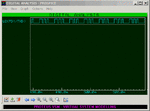
pls check the image above I dont know but I manage to adjust the wave form ..

---------- Post added at 18:08 ---------- Previous post was at 18:06 ----------

that was from the SCK PIN..
 
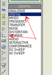
Click the icon in the picture and select digital graph

dgraph.gif

Then click on the schematic open the square and click again to create the graph.
Then place the voltage probe on the SCK net and drag & drop it in the graph.
The graph has a duration of 1sec by default, right click and select edit graph to change it.
Go over the graph and press space bar to run

Alex

To maximize the graph double click on the graph header, the green part at the top, then you will have the zoom tools available

max_graph.gif

max_graph2.gif
 
Hi guys.. its now working.. :) I tried to interface it to TC72 SPI temperature sensor.
I have this doubt in my mind.. i think I cannot test the SPI operation without another device..hmm I confuse I dont know what is correct...lol
I did not change my configuration I just use the same code but this time I apply it to another SPI device as slave... I dont know but though Im happy.. lol


**broken link removed**
 
Last edited:

Well, at least you know your routines were written correctly.

Or did you use the Hi-Tech PIC18 Libraries?

What was the first device you attempted to interface with SPI?
 
Well, at least you know your routines were written correctly.

Or did you use the Hi-Tech PIC18 Libraries?

What was the first device you attempted to interface with SPI?


I write my own functions based on my understanding how SPI works as described in the datasheet.


My code is very basic... take a look.. I interface it using TCP72 SPI temperature sensor

I doubt that my previous code doesn't work because I did not test it with other device.. hmmm anyway I have my next target.. I will try to write/read in SDcard..


PHP:
#include<htc.h>


unsigned char msb , lsb;
unsigned int x,y;

void spi_init();
unsigned char read_sensor();
void spi_init();

void main()
{
	spi_init();
	TRISD = 0;
	
	while(1)
	{
		
		PORTD = read_sensor();
		for(y=0; y<5000; y++);
	}


}

void spi_init()
{
	SMP = 1; //Input data sampled at end of data output time
	CKE = 0; //Transmit occurs on transition from Idle to active clock state
	CKP = 0; //Idle state for clock is a low level
	SSPEN = 1; //Enables serial port and configures SCK, SDO, SDI and SS as serial port pins
	SSPCON1 |= 0b0000; // SPI Master mode, clock = FOSC/4

	TRISCbits.RC7 = 0; //Serial Data Out (SDO)
	TRISBbits.RB0 = 1; //Serial Data In (SDI)
	TRISBbits.RB1 = 0; //Serial Clock (SCK)
	TRISCbits.RC0 = 0; //chip select

}


void spi_send(unsigned char data)
{
	SSPBUF = data;
	while(!BF);

}

unsigned char read_sensor()
{	
	
	char dummy;

	RC0 = 1; // Enable sensor
	spi_send(0x80);
//	dummy = SSPBUF;
	spi_send(0x11);
	RC0 = 0;
//	dummy = SSPBUF;
	for(x=0; x<3000; x++);
	RC0 = 1;
	spi_send(0x02); //Read MSB temperature address
//	dummy = SSPBUF;
	spi_send(0x00); //Read temperature high 
	msb = SSPBUF;
	spi_send(0x00);
	lsb = SSPBUF;
	RC0 = 0;
	return msb;
	
}
 
Last edited:

I write my own functions based on my understanding how SPI works as described in the datasheet.


My code is very basic... take a look.. I interface it using TCP72 SPI temperature sensor

I doubt that my previous code doesn't work because I did not test it with other device.. hmmm anyway I have my next target.. I will try to write/read in SDcard..


With live hardware or simulation? How about trying a SPI EEPROM?
 
With live hardware or simulation? How about trying a SPI EEPROM?


only simulation.. :) I will checkout my order this night(PIC18f4550).. will try it in hardware..

so when I try it in hardware no more configurations except fuse bits? hmm hehe
 

I think you might find the 18F4550 a little more challenging in actual hardware, but we'll see.

Proteus is very forgiving as far as the little details, compared to implementing an actual circuit in physical hardware.
 
Last edited:
I think you might find the 18F4550 a little more challenging in actual hardware, but we'll see.

Proteus is very forgiving as far as the little details, compared to implementing an actual circuit in physical hardware.

hmm that's what Im afraid of.. I hope I can do a simple blink of led when I have this PIC..

---------- Post added at 07:15 ---------- Previous post was at 07:13 ----------

Its hard to simulate SPI protocol without the actual hardware.. so you need an external interface to get the communication and see the output.........

yes I think based on experience..

---------- Post added at 07:16 ---------- Previous post was at 07:15 ----------

With live hardware or simulation? How about trying a SPI EEPROM?

I will try this also for sure..
 

There is an SPI debugger in proteus , connect the Din, Dout, SCK, SS and you can easily see the spi bytes that were transmitted and if the timings were valid, you can also use it while there are other spi devices connected to the mcu.
There are also many eeprom models, you can connect any of them and watch the internal eeprom memory as it is written (from the debug menu show spi memory of the chip)
To clear the eeprom contents (because they are persistent in the eeprom case) go to debug menu -> reset persistent model data

Alex
 
There is an SPI debugger in proteus , connect the Din, Dout, SCK, SS and you can easily see the spi bytes that were transmitted and if the timings were valid, you can also use it while there are other spi devices connected to the mcu.

**broken link removed**


Yes.. thanks.. I just knew how to read the SPI debugger :) .. I was confused before why I can see only time in the window :) but it is along with the data received and transmitted..


There are also many eeprom models, you can connect any of them and watch the internal eeprom memory as it is written (from the debug menu show spi memory of the chip)
To clear the eeprom contents (because they are persistent in the eeprom case) go to debug menu -> reset persistent model data

I will try this when I worked with EEPROM.. thanks
this week I have my exams in school I might continue my learning here next next week...

thanks all of you guys here for helping me :smile:
 

Hi Romel,

Here is a site with quite a few excellent Hi-Tech C Compiler specific examples:

MicrochipC.com PIC Micros and C

It is the source of the SPI examples I uploaded for you earlier, I finally figured out where I originally found them. I looked briefly through the thread to see if someone had already provided this link, but it has gotten quite long, so pardon me if you already have it.

MicrochipC has excellent reusable modules which I have used in many projects.

Ciao
 
Status
Not open for further replies.

Part and Inventory Search

Welcome to EDABoard.com

Sponsor

Back
Top