Continue to Site

Welcome to EDAboard.com

Welcome to our site! EDAboard.com is an international Electronics Discussion Forum focused on EDA software, circuits, schematics, books, theory, papers, asic, pld, 8051, DSP, Network, RF, Analog Design, PCB, Service Manuals... and a whole lot more! To participate you need to register. Registration is free. Click here to register now.

[ASK] Bandpass filter Frequency shift after layout and schematic co-simulation in ADS

Status
Not open for further replies.

rhyando

Newbie level 4
Joined
Dec 28, 2010
Messages
6
Helped
0
Reputation
0
Reaction score
0
Trophy points
1,281
Activity points
1,323
Hello.

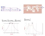
I've made an bandpass filter in schematic and the frequency responce is good (left picture in attachment pic) Spec = f0=145.95 MHz, BW = 20 MHz, Type:butterworth.

But when i simulate the transmission line as shown in the pic in right side with fr4, er=4.2, thickness=1.6mm, dan tand=0.02. I get frequency shifting in ADS simulation. Why is this happen ? what can i do to minimize the transmission line effect in ADS ?

can anyone help me ?

thanks.
clipboard1-tile.jpg
 

Keep your lines as short as you can, or include them in your design.

The 3nH inductor LP3 is very sensitive to extra length in that path. I would implement that as a piece of line (a few mm will give 3nH). Do not forget that the via to ground is also part of that inductor.

Another important aspect are the parasitics in your SMD elements. From what I have seen, you have simulated with ideal L/C so far. Have a look at the equivalent circuit models and/or *.s2p models from the component manufacturer.
 

Some of your components (like 3.7 nH coil) are a bit unrealistic at 145 MHz. The unload Q will be bad. The PCB short transmission lines at 145 MHz are pretty much just contributing additional stray capacitance to ground, the most damaging being the 0.7 pF or so PCB stray to ground between your series 1.8 pF/644 nH coupling resonators. If you design for higher termination impedance you will get more realistic component values.

14% bandwidth is achievable with just capacitance top coupled parallel tanks. It is near the limit but do-able.

Your model does not include effects of Q of components, primarily the coils, which will change the design quite a bit. A tank with 3.7 nH and 325 pF resonanting capacitance will have a very low unloaded Q, probably in range of 20 to 25. Probably below the minimum necessary to make the five pole filter design.
 
Last edited:

Your layout is completely wrong..
 
  • Like
Reactions: Saadw

    Saadw

    Points: 2
    Helpful Answer Positive Rating
Status
Not open for further replies.

Part and Inventory Search

Welcome to EDABoard.com

Sponsor

Back
Top