Continue to Site

Welcome to EDAboard.com

Welcome to our site! EDAboard.com is an international Electronics Discussion Forum focused on EDA software, circuits, schematics, books, theory, papers, asic, pld, 8051, DSP, Network, RF, Analog Design, PCB, Service Manuals... and a whole lot more! To participate you need to register. Registration is free. Click here to register now.

Sensorless 3-Phase Brushless DC Motor Driver 10A, 15000RPM, HELP

Status
Not open for further replies.

atakan_1907

Junior Member level 3
Joined
Feb 23, 2009
Messages
28
Helped
0
Reputation
0
Reaction score
0
Trophy points
1,281
Location
Bursa, Türkiye
Activity points
1,487
Hi All,

Could you assist me to build a sensorless motor driver please.
This is very urgent.

Specs:
  1. 3 phase DC motor (E-max CF2212 datasheet)
  2. 11.1v nominal (3S lithium polymer)
  3. 0.15Ω internal resistance of motor
  4. Up to 15000 RPM
  5. Up to 12A

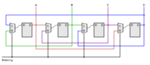
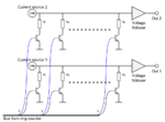
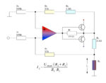
A pic will give analog (dac) output to determine motor torque (or simply current). And rest of drive process will be handled by hardware. I prefer to use seperate and small parts instead of combo driver ic's.

Please help me, assist me. Dont give me complex circuits that i cant understand. Please take it simple.
 

I can always assist you in how to make it run. It's pretty simple. You need to feed it with three phase voltage. I would recomend feed it with constant current then.
This way, the motor will run. But it can stall if a sudden change in torque occur.

To make the controller in a way so the motor don't stall, require some sort of feedback from the motor to the controller. That's the hard part.
 
I think we have to take feedback from the back emf of undriven (3th) phase. I think we can drive it using logic gates, oscillator (for pwm) and comparators.
Do you mean 3 phase mains? No! I'll run it with three lipo batteries :)
Could you give me a simple schematic?
 

I did some work for a very simple controller to step motors. However you should be able to modify it for use with 3 phase dc motor.

As you can see, I'm not a µPC guy, but I build it from discrete components.

I have uploaded some of my own drawings, made for running a stepper. It's just a set with drawings, but it should make it possible for you to build a working controller.

However it doesn't have any feedback controller, and I doesn't know how to implement it. Hopefully some other on the forum can help.
 

Attachments

  • ringteller-BIDIR_4.png
    ringteller-BIDIR_4.png
    13.6 KB · Views: 92
  • sinus_Rgrid_2.png
    sinus_Rgrid_2.png
    40.5 KB · Views: 89
  • Stepper.png
    Stepper.png
    12.8 KB · Views: 95
  • BidirectionalCurrentSource.png
    BidirectionalCurrentSource.png
    30.3 KB · Views: 134
But stepper motors have not the same principle :(
I need back emf feedback from the undriven phase to advance the commutation.
And one more thing, if my motor has 0.15 ohm internal resistance and Rds(on) of mosfets (irfp460 for example) at about 0.3ohms, isn't there a problem?
Help :)
 

And one more thing, if my motor has 0.15 ohm internal resistance and Rds(on) of mosfets (irfp460 for example) at about 0.3ohms, isn't there a problem?
Yes there is. That's why I tell you to make a constant current output.
As a simple solution, you can sue my drawing as a base. However, if you're planning to use pwm, you need another circuit.
 

Status
Not open for further replies.

Similar threads

Part and Inventory Search

Welcome to EDABoard.com

Sponsor

Back
Top