Continue to Site

Welcome to EDAboard.com

Welcome to our site! EDAboard.com is an international Electronics Discussion Forum focused on EDA software, circuits, schematics, books, theory, papers, asic, pld, 8051, DSP, Network, RF, Analog Design, PCB, Service Manuals... and a whole lot more! To participate you need to register. Registration is free. Click here to register now.

[SOLVED] Modes in Circular Waveguide

Status
Not open for further replies.

redcrystalline

Advanced Member level 4
Joined
Nov 10, 2010
Messages
117
Helped
13
Reputation
26
Reaction score
13
Trophy points
1,298
Activity points
1,882
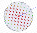
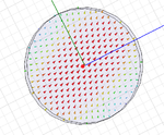
Hi, my problem is about 1st and 2th modes in circular waveguide, it seems that this two are same mode in addition the cutoff frequencies are not matched with analytical calculation,i've attached project, whats the problem ?
mode2.png
mode1.png
View attachment circular waveguide.rar
Best Regards
Iman Akbari
 

Circular waveguides along with square waveguides have degenerate modes due to the geometrical symmetry. Therefore, though the first two modes are orthogonal and indeed represent the first two modes, they have the same cutoff frequency and the same impedance. The only difference is their polarizations (due to azimuthal solution), which of course are orthogonal to one another.

Have Fun
 
thank for your answer, but what about other modes? i mean that i expect that have 2 cutoff frequency under 5 Ghz but in this case all cutoff frequency are above 6Ghz,
thanks again for your patient,
 

The cutoff frequency for this waveguide is ~6.55GHz. Also, for this analysis, dont plot S12. It is best to plot Real and Imaginary Gamma and observe when Im Gamma becomes greater than zero. You also only need to do a ports only solution for this...much faster. I would check your math one more time to ensure you did not make a mistake. Here is a quick reference: **broken link removed**

Also, to increase accuracy of HFSS for these simulations, go to HFSS->Mesh Operations->Initial Mesh Settings and change the default Surface Normal Deviation from 22.5degrees to, say, 5degrees. When I solve this I get a cutoff that corresponds closely to the theoretical as per the website.

have Fun

Later
 
yes i had a mistake about cutoff frequency calculation.
by the way ,why dont work with s12 or s21 ?_
im using Advanced Engineering Electromagnetics (balanis) book and i have not faced with degenerate modes due to the geometrical symmetry could you give me a source book please?
thanks so much ,you a real generous man,
vielen dank.
 

about "geometrical symmetry" i get it,what that made me confuse was balanis did not mentioned it, but im not still satisfy about this subject that s12 and s21 are not suitable for detecting cutoff frequency.
Best Regards
 

It is not that S parameters are not suitable...It is just that if you care about cutoff frequencies or any other property of a waveguide mode, that is inherently a waveguide property and specifically a property of the propagation constant. If the imaginary part of gamma is greater than zero, then there is a propagating mode. It is very simple to analyze. If you use S parameters, which of course you can, you end up having to make sure that your waveguide is long enough that you can reliably recognize an evanescent mode as it will be sufficiently decayed by the time it reaches your second port. There are cases of modes that although decayed, have a long decay constant and this can confuse one if not prepared for such a mode. Also, a port solution is simply a 2D solution while the S parameter solution is a full 3D solution which is more expensive in time and resources.

You can do either one...I suggest the port solution.

Bitte Sehr
 
you're right ,thanks for your attention and your answer, all your answer are useful .
wish you best.
 
  • Like
Reactions: alex.

    alex.

    Points: 2
    Helpful Answer Positive Rating
Status
Not open for further replies.

Part and Inventory Search

Welcome to EDABoard.com

Sponsor

Back
Top