Continue to Site

Welcome to EDAboard.com

Welcome to our site! EDAboard.com is an international Electronics Discussion Forum focused on EDA software, circuits, schematics, books, theory, papers, asic, pld, 8051, DSP, Network, RF, Analog Design, PCB, Service Manuals... and a whole lot more! To participate you need to register. Registration is free. Click here to register now.

[SOLVED] Is this emergency light circuit correct?

Status
Not open for further replies.

Rabiuls

Junior Member level 1
Joined
May 26, 2010
Messages
18
Helped
1
Reputation
2
Reaction score
1
Trophy points
1,283
Activity points
1,425
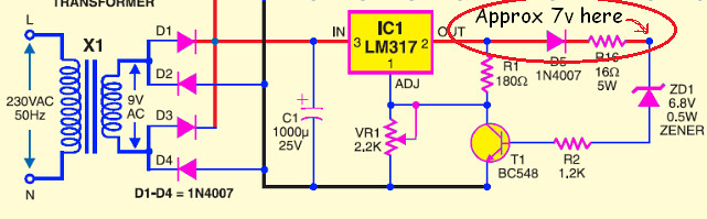
I found this circuit on the web. Many web pages have this circuit. Google for EMERGENCY LIGHT schematic - Google Search and you will find it. Anyway, the circuit is given bellow:

25aoj9e.png


This is mentioned that the circuit will protect the battery from overcharging as - "... When the battery gets charged to 6.8V, zener diode ZD1 conducts and charging current from regulator IC1 finds a path through transistor T1 to ground and it stops charging of the battery."

I think even if the battery voltage is bellow 6.8, ZD1 gets minimum 6.8v from the IC1 through D5. So, the said ZD1 conducts if there is output from IC1 and battery voltage does not matter at all in stopping the overcharging.

Am I wrong or missing something?

Thanks a lot.
 

I think the circuit will work just fine.

The zener diode voltage will approximately track the voltage on the battery. The zener doesn't conduct any current until it's voltage reaches around 6.8V... in essence, it looks like a capacitor until the battery voltage gets close to 6.8V. Once the battery voltage gets to around 6.8V, then ZD1 begins to conduct, which turns on T1, which pulls the ADJ pin down, backing off the regulator until very little current comes out.
 

Thanks enjunear.
But even if the battery voltage is low, for example say 2 volts, the zener will get 6.8 volts from the IC1 input. So, it will conduct. Is that right?
 

Actually the voltage won’t be 6.8 but in theory 6.8+U[R2]+U[BE] what in practice roughly comes up to 7.2V, as the U[R2] can be neglected and the Zener will start to conduct small current starting from roughly 6.6-6.7V ..
7.2V is the voltage of fully-charged battery and it will be the equilibrium .. and the charging current should drop to almost next to nothing ..

IanP
:wink:
 

Thanks IanP.
Still confused :?

This part of the circuit is to stop charging the battery if voltage reaches at least 6.8. But this voltage or more (sure it is more) is always there.

I am posting another image without the battery part for easy understanding. Will it react with the battery volt at all? As approximately 7 volts is always there from the LM-317 regulator.

5602346330_e0f3ea9a42_b.jpg
 

Will it react with the battery volt at all? As approximately 7 volts is always there from the LM-317 regulator.

As soon as transistor starts to receive current through the Zener diode it will pull down the voltage on the ADJ pin of the LM317n and the voltage on the output pin of the regulator will itself adjust to roughly 7.2V, so no current will flow through diode-resistor to the battery .. end of story ..

IanP
:wink:
 

I think even if the battery voltage is bellow 6.8, ZD1 gets minimum 6.8v from the IC1 through D5. So, the said ZD1 conducts if there is output from IC1 and battery voltage does not matter at all in stopping the overcharging.

Am I wrong or missing something?

You are wrong and missing something.

The battery voltage does matter.

If the battery is discharged to, say, 5V, then irrespective of IC1's output, there will be 5V at the zener's cathode. (And that will be true whatever the battery voltage happens to be.)

The difference between the battery voltage and IC1's output is dropped across D5 and R16.

As the battery receives charge, its voltage increases, the voltage difference between IC1's output and the battery reduces, and the charging current reduces accordingly.

This contunues, with the battery voltage slowly increasing and the current into it slowly decreasing, until the voltage across the battery equals the zener voltage of approximately 6.8 (it's not exact), plus Vbe of T1.

At that point the zener will be starting to conduct .....
 
Thank you Syncopator. That's the exact answer.

I was wrong in calculating the voltage in parallel connection. This was new for me. Still I am not clear about the voltage calculation for parallel connection (not the circuit, now the circuit part is clear). I am testing this on simulator and various result shown for slight change. For example, if I put a resistor on the battery side, voltage on zener increases (while I thought it would decrease). Interesting, anyway that is not related to the circuit or this thread. Thanks again.
 

... For example, if I put a resistor on the battery side, voltage on zener increases (while I thought it would decrease)

This simplified diagram shows a voltage distribution across the relevant components (I'm guessing at the regulator's output, but it serves the purpose.)

ledbat1.gif


Adding a resistor "on the battery side" like this, changes the voltage distrubution, (The value of the additional resistor chosen simply because it's convenient.)

ledbat2.gif


Perhaps this helps?
 
Last edited:
Indeed that's a great help :grin:
Thanks a lot Syncopator.
 

there is no need for a 16 ohm 5W resistor , 6.8V zener diode, R2 1.2K, and transistor T1 BC548
Just calculate the LM317 resistors required to get 7.6 volts at its output
Vo=1.25[1+R2/R1] where R1 is the resistor from OUT to ADJ pin and R2 is the resistor from ADJ to ground
for R1=150 ohms 1/4 watt set R2 at 762 ohms with VR1 and use 1N4007 in series to get 7 volts at battery + terminal
 
Andy G, if the components are removed then it will only charge the battery, but not protect the battery from overcharging. It is not good for the battery to overcharge.

So, if you put the components, then when the battery is charged that means, when it reaches to a minimum voltage 6.8, current will start flowing through the zener diode ZD1. It will trigger the transistor - T1. And now almost all the current will drain through the transistor's collector and emitter. Not enough to charge the battery anymore.
 
Hi! Rabiuls
the 6.8V zener circuit seems like a paradox to me, as when the output of LM317T gives 7 volts at the battery terminal the T1 BC548 transistor shuts down the voltage output of LM317T so how the battery will be charged?
At a constant +7 volts at battery terminal from IC1 the battery will not be overcharged.
You will not find this arrangement in Chinese emergency lamps available in the market
 
Hi Andy G,
the 6.8V zener circuit seems like a paradox to me, as when the output of LM317T gives 7 volts at the battery terminal the T1 BC548 transistor shuts down

It was same for me too. Say, the battery got slightly discharged and now the volt is 5. And the LM-317 is supplying 7 volts. So, what is the volt on zener? 7v, as the output of LM-317. Perhaps this is what you think, like me. But it is not correct. Voltage on the zener will be 5. See the image bellow, what happens to voltage when batteries are connected in parallel:

5609283510_613391e910_z.jpg


See Syncopator's reply above for explanation.

Now, when the battery is 5v, voltage on zener diode is 5v. And this is a 6.8 zener diode. So, it allows current to flow only when the voltage is greater than 6.8. This happens when the zener is connected in reverse direction, which is connected for this circuit.

This way, the battery gets charged and voltage increases. When voltage gets greater than 6.8 volts, current starts flowing through the transistor base. Which now drains the LM-317 output and battery does not get anything to get charged - overcharged.

The D5 prevents the battery getting discharged through this path. This is my understanding so far.

Regards.
 

Thanks Rabiuls for the explanation, indeed there is a lot to learn.
regards
 

Status
Not open for further replies.

Similar threads

Part and Inventory Search

Welcome to EDABoard.com

Sponsor

Back
Top