Continue to Site

Welcome to EDAboard.com

Welcome to our site! EDAboard.com is an international Electronics Discussion Forum focused on EDA software, circuits, schematics, books, theory, papers, asic, pld, 8051, DSP, Network, RF, Analog Design, PCB, Service Manuals... and a whole lot more! To participate you need to register. Registration is free. Click here to register now.

Strange OA problems -

Status
Not open for further replies.

uoficowboy

Full Member level 3
Joined
Apr 4, 2009
Messages
169
Helped
6
Reputation
12
Reaction score
5
Trophy points
1,298
Location
Seattle, Wa, USA
Activity points
2,964
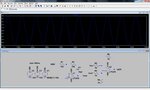
Hi - the circuit shown works just fine. I'm trying to make a basic proof of concept PI controller circuit.

However, if I change R3 and R4 to 10K resistors, the circuit oscillates like crazy.

Can anybody explain this? My only guess is that it is due to the bias current of the OA inputs?

The .txt file should be renamed to be a .asc file - then you can run it in ltspice.

Thanks!
 

Attachments

  • PI-Problems.jpg
    PI-Problems.jpg
    115 KB · Views: 84
  • CCCV.txt
    1.9 KB · Views: 56

It might be because of the input capacitance of the OpAmp, but oscillation frequency is to low for this. It also can be because of the OA self transfer function.
Try to put a resistor in series to the OA output (before feedback closure).
 
the circuit oscillates like crazy
Hm. You are giving a 100 Hz sine on the circuit input and get an amplified 100 Hz output. What's strange?

P.S.: You didn't tell, that the waveform doesn't show the output of the present circuit. It's actually unstable. Sketching a bode diagram of the overall loop gain reveals why. If you reduce the gain, the circuit will be stable.

To realize the integrator gain set by 1/(100 ohm * 10 pF), the OP needs a gain-bandwidth product of 160 MHz. Of course it hasn't, so it's simply operating open loop.
 
Last edited:
Hm. You are giving a 100 Hz sine on the circuit input and get an amplified 100 Hz output. What's strange?

P.S.: You didn't tell, that the waveform doesn't show the output of the present circuit. It's actually unstable. Sketching a bode diagram of the overall loop gain reveals why. If you reduce the gain, the circuit will be stable.

To realize the integrator gain set by 1/(100 ohm * 10 pF), the OP needs a gain-bandwidth product of 160 MHz. Of course it hasn't, so it's simply operating open loop.
Hi FvM -

I'm sorry I was not more clear - the waveform is showing the output of the circuit as it is drawn. The circuit is operating how I expect it to there. I included the .asc file (renamed as .txt) so that this can be verified. However, if I change the values of R3 and R4, my output will oscillate badly.

So I'm getting the pole of the transfer function to be at (R1 + 1) / (R2C1) rad/s, and the zero to be at 1 / (R2C1) rad/sec. And that is way faster than my OA. So I see that that is a problem. When I increase R2 and C1 each by a factor of 10, the circuit still operates as expected. However, I still can't change R5 and R6 to 10K - the circuit starts to oscillate when I make that change, even if I've slowed down the pole and the zero.

I suspect this is an overly simple question - but how do you find the integrator gain?

Thanks!
 

I see, that you know how to calculate the (ideal) transfer function of the PI circuit. So you can see, that the ideal transfer function is void, because the OP open loop gain is lower for any frequency. So effectively you get an overall loop gain formed by the open loop gain of the "PI" OP and the gain of the differential amplifier, resulting in an unity gain frequency at 1/2 OP bandwidth and about zero (or negative) phase margin. That's a perfect oscillator.

You would want to dimension the PI stage in a way, that a much lower unity gain frequency and sufficient phase margin is achieved.

P.S.: In addition, if you use a fast OP for the PI stage, so that the P gain of 100 can be realized, then the circuit will be unstable as well.
 
Last edited:
I see, that you know how to calculate the (ideal) transfer function of the PI circuit. So you can see, that the ideal transfer function is void, because the OP open loop gain is lower for any frequency. So effectively you get an overall loop gain formed by the open loop gain of the "PI" OP and the gain of the differential amplifier, resulting in an unity gain frequency at 1/2 OP bandwidth and about zero (or negative) phase margin. That's a perfect oscillator.

You would want to dimension the PI stage in a way, that a much lower unity gain frequency and sufficient phase margin is achieved.

P.S.: In addition, if you use a fast OP for the PI stage, so that the P gain of 100 can be realized, then the circuit will be unstable as well.
Hi FvM - thanks for your patience :)

What do you mean by "dimension the PI stage"? Are you referring to changing the P and I gains? How do you determine what the P and I gains are?

Thanks!
 

As a supplement, you previously mentioned a pole of the PI stage. The ideal PI circuit has no pole (only the finite OP gain introduces it).

How do you determine what the P and I gains are?
In my understanding, the P gain is -R2/R1 and the I gain -1/jωR1C.

Basically, I don't see a use for the P term with the present "control process model". The only way to get it stable to reduce the "controller" gain considerably, effectively using pure I controller action.

But I assume, you have some basic ideas about PI controller design. Analyse the transfer function of the given circuit and try to achieve stability.
 
As a supplement, you previously mentioned a pole of the PI stage. The ideal PI circuit has no pole (only the finite OP gain introduces it).


In my understanding, the P gain is -R2/R1 and the I gain -1/jωR1C.

Basically, I don't see a use for the P term with the present "control process model". The only way to get it stable to reduce the "controller" gain considerably, effectively using pure I controller action.

But I assume, you have some basic ideas about PI controller design. Analyse the transfer function of the given circuit and try to achieve stability.
Hi FvM - the open loop transfer function that I calculate for the PI controller has only a zero as you say. So I think it is OK, yes? I only see a zero when I find the closed loop transfer function.

The open loop function is: -(R2/R1) - 1/(R1C1S), so Kp = -R2/R1, Ki = -1/(R1C1)

I have done PID controller turning many years ago. It has been a while no doubt!

I did just now discover that I messed up my math a bit.

I get the final transfer function to be: (R2/(R1+R2)) * (s+(1/(R2C1)))/(s+1/((R1+R2)C1))

So zero at 1/(R2C1) rad/sec and pole at 1/((R1+R2)C1) rad/sec.
 
Last edited:

Status
Not open for further replies.

Similar threads

Part and Inventory Search

Welcome to EDABoard.com

Sponsor

Back
Top