Continue to Site

Welcome to EDAboard.com

Welcome to our site! EDAboard.com is an international Electronics Discussion Forum focused on EDA software, circuits, schematics, books, theory, papers, asic, pld, 8051, DSP, Network, RF, Analog Design, PCB, Service Manuals... and a whole lot more! To participate you need to register. Registration is free. Click here to register now.

RC Snubber leakage current.

Status
Not open for further replies.

circuit_freak

Junior Member level 1
Joined
Feb 20, 2011
Messages
16
Helped
0
Reputation
0
Reaction score
0
Trophy points
1,281
Activity points
1,395
Hi guys,

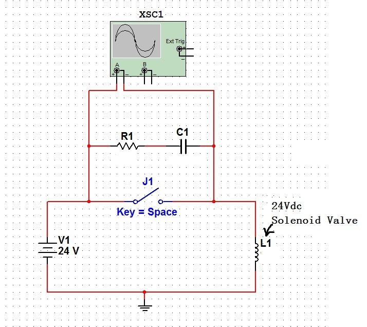
From what I read they said there is leakage current in RC snubber when it connects parallel with switch.
But in simulation, the ammeter doesnt show any leakage current.


Anyone has any practical experience for above case?
If I want to build the circuit as shown above any type 100ohm resistor and 100nF capacitor will do the job right?

Thanks
 

I guess, you have read about leakage with AC supply. There's no leakage current for DC.
 

ok, this makes sense. thanks FVM
nextly I want to do testing on breadboard, can you recommend which type of R and C i should select.
a 24Vdc pneumatic solenoid valve will be the inductive load for this testing.

tq
 

There's no leakage current for DC.


if you say about the above circuit then i may agree... but if you say there is no DC leakage current , then i may not agree with you... there exists DC leakage current..

Please see this
Dc leakage current usually applies only to end-product equipment, not to power supplies.
Ac leakage current is caused by a parallel combination of capacitance and dc resistance between a voltage source (ac line) and the grounded conductive parts of the equipment. The leakage caused by the dc resistance usually is insignificant compared to the ac impedance of various parallel capacitances. The capacitance may be intentional (such as in EMI filter capacitors) or unintentional.

We at yokogawa develop tester to measure both AC and DC leakage currents. but i dont understand the context of your answer..
 

Despite your verbose explanation, there's no leakage current present in the discussed circuit. Please notice the specific question of the original poster.

P.S.: The fact, that leakage current is a technical term in safety regulations doesn't imply, that you can't use it in different relations. You should hear for the specific problem, not a word.
 
Last edited:

ok, this makes sense. thanks FVM
nextly I want to do testing on breadboard, can you recommend which type of R and C i should select.
a 24Vdc pneumatic solenoid valve will be the inductive load for this testing.

tq

any idea with above? thanks
 

FvM, maybe I'm missing something, but why do you say there will be no leakage current? The capacitor will have some parasitic parallel resistance which will allow some leakage. It may not be modeled in circuit_freak's simulation so he doesn't see any, but in practice wouldn't you expect to have some?


can you recommend which type of R and C i should select.
a 24Vdc pneumatic solenoid valve will be the inductive load for this testing.

This really depends on the specs of your solenoid.
 

The capacitor will have some parasitic parallel resistance which will allow some leakage.
Yes, some leakage. But in my opinion, we should focus on currents of practical relevance.

You'll find specification for typical leakage resistance values of foil capcacitors in a 10^11 - 10^12 ohm (Teraohm) order of magnitude. Thus it's questionable, if the PCB surface, the relay contact or the capacitor have a higher leakage current. Most likely, the PCB surface.
 

FvM, yes I absolutely agree it's practically negligible. I just wasn't sure if the OP was looking at it from a theoretical or practical standpoint, since he was discussing a simulation.
 

hi, i have build the circuit to switch a 24Vdc solenoid valve as shown previously.

when the switch open i can see a voltage transient to around 70V using oscilloscope.
waveform as shown below.


But when i install a RC parallel to the switch the spike remain (no changes at all)

I did try with various value as below but no luck the spike still there.
R (Axial-lead Resistor - 150ohm, 100ohm, 47ohm & 22ohm)
C (Ceramic Disc Capacitor - 0.1uF & 0.01uF)


did i miss out something?

thanks in advance.
 
Last edited:

There are two possible reasons:
- The snubber resistor is too high related to the the load current. 22 or 47 ohm sound reasonable, however.
- The capacitance is too low related to the load inductance (L/R time constant).

P.S.: You may want to tell the timebase for the waveform.
 

Circuit_freak, what is the scope trace showing (motor, switch)? You mentioned this transient happens when the switch opens. If so, I would agree with FvW that your values should be adjusted, and you might also want to try using a diode snubber in addition to (or instead of) the RC snubber. This is essentially a flyback diode reverse-biased in parallel with the motor. If your scope trace is showing the motor voltage (the transient is coming when the switch closes), maybe it's inrush current and perhaps a series inductor would help.
 
  • Like
Reactions: FvM

    FvM

    Points: 2
    Helpful Answer Positive Rating
hi, my circuit is as below.


The probe is connected parallel to the switch and RC snubber.
and the current flow to the solenoid is around 17mA.
Transient shown previously happens when the switch opened.


FvM - i have forgotten the timebase will check and update you.
so ill stick with 22ohm 0.5W resistor and try with 1uF & 10uF (radial capacitor) later.

ARQuattr - i tried diode snubber before and it was great, and i wanna know more about rc snubber that why this circuit is made. :-D

thanks
 

Status
Not open for further replies.

Part and Inventory Search

Welcome to EDABoard.com

Sponsor

Back
Top