Continue to Site

Welcome to EDAboard.com

Welcome to our site! EDAboard.com is an international Electronics Discussion Forum focused on EDA software, circuits, schematics, books, theory, papers, asic, pld, 8051, DSP, Network, RF, Analog Design, PCB, Service Manuals... and a whole lot more! To participate you need to register. Registration is free. Click here to register now.

RF chokes when using plasma probes

Status
Not open for further replies.

grega_primc

Newbie level 5
Joined
Feb 17, 2011
Messages
10
Helped
0
Reputation
0
Reaction score
0
Trophy points
1,281
Activity points
1,359
Hey,

I am working with plasma and deal with measuring plasma particle densities. We use simple electric or Langmuir probes, which we put into plasma to measure the current picked up by the probe. The probe is then connected to the oscilloscope, where we measure current through voltage.
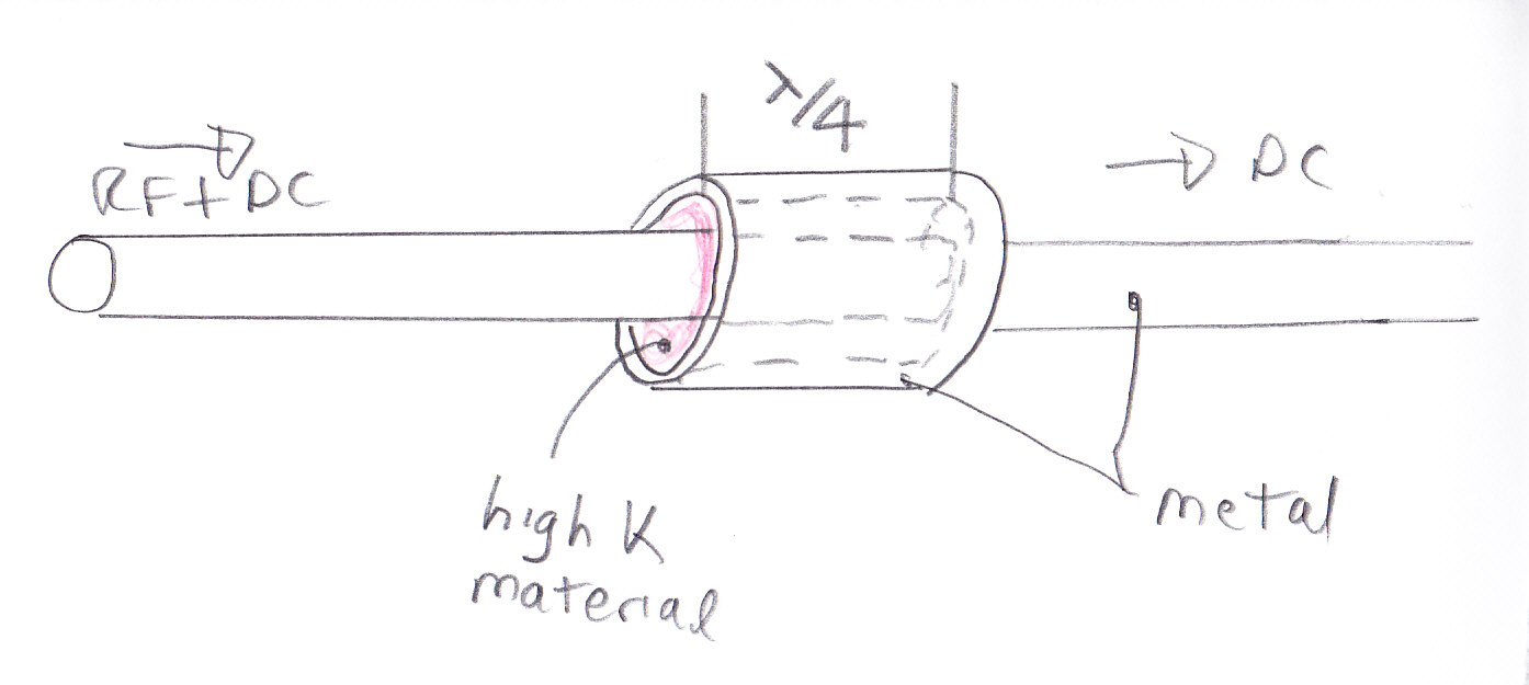
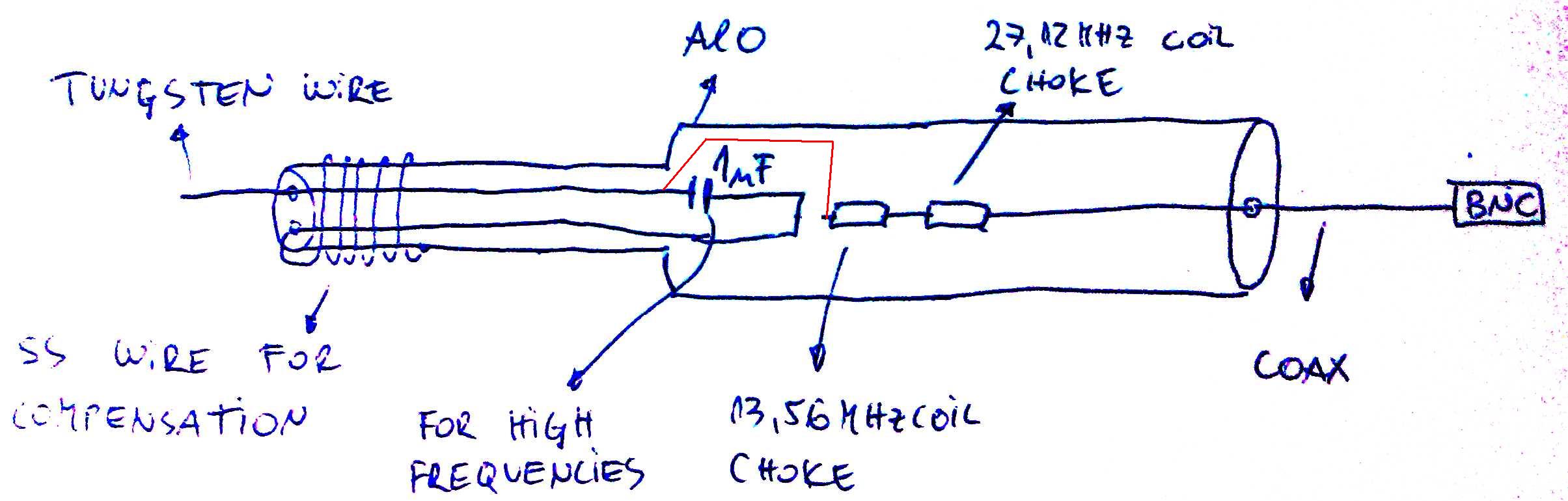
Plasma is created with an RF generator operating usually at frequency 13.56 MHz. And the probe in the plasma reacts as an antenna picking up lots of 13.56 and 27.12 MHz signals, which spoiles the probe charasteristics.
I will try to use chokes, to cut off these two frequencies where the coax cable of the probe begins. The problem is that I don't know the impedance of plasma, because it changes when using different excitation powers or gas pressure or..., and the plasma impedance cannot be determined. The probe impedance is always the same and it is around 10 Ω, but then again the probe is all the time coupled to the plasma.

Have any suggestions?

Thanks,
Regards
 

Hello,

I'm sure many people on this forum have the knowledge to give you useful info, but not all are working in plasma physics.

Maybe you can provide us some additional info, as the effectiveness of chokes depends on the impedance they see left and right of them. I Assume that you are thinking of series or parallel resonant narrow band chokes (for example two parallel resonant circuits in series).

Is your signal to be measured DC, slow varying DC, RF, etc?
 

You do not describe the probes. If it is a single wire probe, I would do something like this:


I would find a high K dielectric (maybe 98 or so). You machine the metal cup depth for quarterwave at 13.56. Since for that dimension, the depth is also around 2 x quarterwave at 27 GHz, it might work well enough for both frequencies.

You could also clamp ferrite beads to the rod, to further attenuate the signal.

If the probe is a 2-wire type, simply make up a differential lowpass filter inside of a tight metal shield box, and run a coax cable from the box to the oscilloscope input.
 

Well plasma is a gas where molecules and atoms are stripped off of outer electrons, so it consists of ions, electrons and neutral particles (atoms and molecules). The probe itself measures ion and electron current, which we see as a probe characteristics. We sweep the probe with certain voltage at low frequency and measure voltage / current of the probe. Yes and the signal is DC.

I think it would be hard to use choke on a wire, since the wire is very thin - around 0.03 mm. It would be possible before attaching the coax cable to oscilloscope to put the choke around coax.

Here is a picture of the probe (the bnc then goes to the oscilloscope):
IMAG0085.jpg

The chokes are drawn where I'd like them to be and maybe add additional two chokes before the signal connects to the oscilloscope.

Regards
 
Last edited:

Hello,

A choke around the coaxial cable does attenuate common mode interference, but when the interference (your 13.56 and 27.12 MHz) is mixed with the DC signal (so it is on the inner conductor of the coaxial cable), these chokes doesn't work.

You have to attenuate the interference with respect to the screen of the coaxial cable. A multi section LPF (low pass filter), or an LPF with notch action on the interfering frequencies should do the job. You can locate this at the input of the oscilloscope

I assume you use a standard 1 MOhm//25 pF input oscilloscope, so leakage through capacitors will not be an issue. Of course the transient response will change due to the capacitors (and inductors).

The chokes inside the probe housing may show bad operation when due to multiple reflections in the coaxial cable, the impedance at the input of the coax (where it connects to the probe) becomes high (it can be kOhms, due to standing wave resonance).

I hope I didn't misunderstand you, as I can't see the DC signal path in the probe drawing.
 
I hope I didn't misunderstand you, as I can't see the DC signal path in the probe drawing.

No, the explanation is fine, thanks. So it is better to put chokes/notch LP filter just before the oscilloscope.
Should I equal the impedance at the end of the probe before connecting to the coax cable or can I just connect the probe to the cable without worrying about matching impedance?

---------- Post added at 09:11 ---------- Previous post was at 09:08 ----------

https://www.minicircuits.com/pdfs/BLP-1.9+.pdf
$35 and you are done. Buy 2 and a 3 dB pad to put between them if you need more rejection.

That's a really cool colution. What do you mean by a 3 dB pad?
 

No, the explanation is fine, thanks.
Yes and the signal is DC.

How? The DC path is cut by the capacitor and the RF path is cut by the 13.56/27.12 MHz filters. So what do you expect to see at the oscilloscope?

P.S.: The below circuit would make sense for me:

 
Last edited:

How? The DC path is cut by the capacitor and the RF path is cut by the 13.56/27.12 MHz filters. So what do you expect to see at the oscilloscope?

Sorry I didn't draw right, my mistake. The capacitor is on the SS wire and the chokes are connected to tungsten wire.
 

Physics meets electronics...

In addition, it would be meaningful to know the frequency range of the signal of interest (DC to ...), because a RC filter may be much more effective in RF supression than a choke.
 

OK. Thing is... the bnc connector connects to a resistor (1k or more, depends on the accuracy we need). The other side of the resistor is connected to a generator, generating low frequency ramp signal.
Then we measure DC voltage on both sides of the resistor - one is probe and the other is ramp. When we subtract both, and taking into account the resistor, we get the current.
 

If not wanting to add a series resistor, I would place a filter capacitor at the BNC side and tune the chokes with individual parallel capacitors to resonate at the said frequencies.
 
I am not sure what a 13MHz and 27Mhz RF choke is. If it is an inductor with self resonance (sharp attenuation near 13 and 27MHz) then you should put a shunt cap between them otherwise the resonance between two SRF inductors might yield unexpected results. I would probably use a ceramic close to 12n to start, this won't effect the DC response.
 
If not wanting to add a series resistor, I would place a filter capacitor at the BNC side and tune the chokes with individual parallel capacitors to resonate at the said frequencies.

Ok, thanks. Where do you mean to put the filter capacitor?

---------- Post added at 15:02 ---------- Previous post was at 15:00 ----------

Yep, the chokes I am refering to is a self resonant inductor.
 

grega_primc

Fvm is correct when he suggests tuning the inductors to resonate at the blocking frequencies with a parallel cap. But it appears you have chosen inductors that have a SRF at these frequencies already, so there is no need to tune. I would put a shunt cap between the two inductors, choose one to have an SRF in between the two inductors. Just a quick look, it seems a ceramic 0603 style cap 100nF should have a SRF close to 20MHz. This would be the most effective use of these parts for a choke. Not as effective if the shunt cap is placed to the left or right of both inductors.

OK, so if I understand all of you right the filtering part should look like this:
Those "boxes" are chokes or coils, which I have to tune to written frequency.
 

Attachments

  • IMAG0010.jpg
    IMAG0010.jpg
    699.7 KB · Views: 168

Well that's what I thought, but my signal is DC. Won't then the cap just charge to whatever DC voltage - then I'll loose contact between the probe and the oscilloscope?
 
Last edited:

Status
Not open for further replies.

Similar threads

Part and Inventory Search

Welcome to EDABoard.com

Sponsor

Back
Top