Continue to Site

Welcome to EDAboard.com

Welcome to our site! EDAboard.com is an international Electronics Discussion Forum focused on EDA software, circuits, schematics, books, theory, papers, asic, pld, 8051, DSP, Network, RF, Analog Design, PCB, Service Manuals... and a whole lot more! To participate you need to register. Registration is free. Click here to register now.

Which circuit is better Schimitt trigger or Window Comparator ?

Status
Not open for further replies.

blooz

Advanced Member level 2
Joined
Dec 29, 2010
Messages
560
Helped
121
Reputation
242
Reaction score
116
Trophy points
1,343
Location
India
Activity points
4,985
hi
Hi
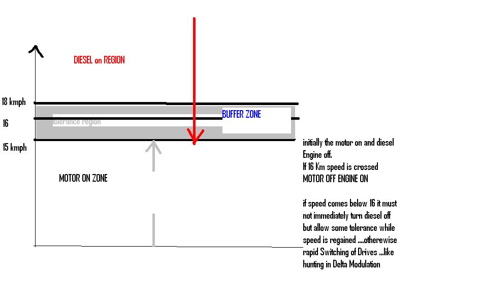
Designing a Motor/Diesel Engine Control System ...

the Require ments are

1.Electric Motor Should be Driving When the velocity is lesser than 15 Kmph

2.If velocity is greater than 15 Kmph the motor Drive is turned off and a Diesel engine is Started ...

3.If the speed of the Drive by Diesel Engine Comes Below 15Kmph with +/-10% tolerance Motor Should be turned on and Diesel turned off.

The Graphical Description is given below ....

Is it Better to use a Schmitt trigger or Go for Window Comparator .......But when Using Window Comparator the logic generated is whether the speed is inside tolerance range or not .....It's not sufficient to control the motor .....Could you help please ...


If you use a window detector, the upper and lower thresholds can be set by individual potentiometers. A schmidt input uses thresholds set by its manufacturers and will be inconvenient to adjust individually.
Frank
 
  • Like
Reactions: blooz

    blooz

    Points: 2
    Helpful Answer Positive Rating
Schmitt gates will be faster and probably lower power (if your
signal spends most of its time away from center - current draw
near threshold is seldom spec'd, because it's not good).

Comparator will be more flexible accurate and sensitive, and
its current draw will be largely independent of input.

Which attributes are more important to you?
 
  • Like
Reactions: blooz

    blooz

    Points: 2
    Helpful Answer Positive Rating
If you use a window detector, the upper and lower thresholds can be set by individual potentiometers. A schmidt input uses thresholds set by its manufacturers and will be inconvenient to adjust individually.
Frank

The same way you can construct a window detector you can construct a comparator with hysteresis, a simpler circuit usually named Schmidt Trigger, for which you can use a pot to set the values.
**broken link removed**
 

Schmitt gates will be faster and probably lower power (if your
signal spends most of its time away from center - current draw
near threshold is seldom spec'd, because it's not good).

Comparator will be more flexible accurate and sensitive, and
its current draw will be largely independent of input.

Which attributes are more important to you?

The System Power Should be low is the primary Requirement.

the output of the comparator is used to turn on and off a motor

the motor should be on until the voltage rises above 9v ......and above that level motor is off ...

During the reverse journey the motor Should be turned on only if voltage falls below 7.5 volt ....can a Schmitt trigger With UTP=9v and LTP=7.5 Do the trick ?

Yes, it can be done with the trip points you have choosen. Current consumption of a comparator circuit can go down to about 1mA depending on the IC you choose. You need to specify the supply and output voltages and currents needed/expected to get a more accurate answer.
 

Yes, it can be done with the trip points you have choosen. Current consumption of a comparator circuit can go down to about 1mA depending on the IC you choose. You need to specify the supply and output voltages and currents needed/expected to get a more accurate answer.

the voltage levels Are
Output is used to turn a Relay via transistor ...the power supply used is 12v battery...Is 555 Ic enough for this or another IC ....? Current Output is a major problem .Inorder to make the things compact the cell used has lower Ampere/Hour rating ... AA cells as power source ...

the output is fed to base of a transistor with a relay ...and the relay Works as a Switch for the 120W motor ..

The 555 wouldn´t be my choice. There are many chips with less power consumption (unless you use a CMOS version). But, before going any further, does the coil of the relay get its power from the batteries? If so it is by far the component that consumes more power. Maybe a solid state relay can help in reducing power. Let us know what are the specs of the relay. Also, you should note that the batteries voltage change as they become discharged. You should have to use some kind of voltage regulator to get stable trip points.
 

Yes you are Absolutely right ......... relay used has ampere rating around 5A ....the Power Source for Motor is A bulkier Battery ...And the idea is to use Separate power source for the schmitt trigger side and relay/ motor side .....Also the output of the comparator is used to trigger a Monostable with width 3Sec Which is connected to the starter Switch of the Diesel Engine ......When the voltage falls below the lower trip point the supply to diesel engine spark plug is cut ....So three Control signals are generated as the output of Schmitt trigger ....

The general picture is

1.When System is just started -

Motor is on ,The Supply to spark plug is off,Monostable out to Diesel Engine Starter is off.

2.When Voltage crosses the upper trigger point ,Motor turned off,Monostable on for 3 sec for starter and Spark plug supply on

3.When the voltage comes below lower trigger point ,motor turned on ,and diesel is turned off by turning off the spark plug supply ..

We Intend to use 555 Cmos Version ...Is there any Better IC ?.....
 

If you are using low voltage CMOS logic there are monostable
multivibrators in the 74xxyyy family. Though there's nothing
wrong with a 555, you would have some more flexible trigger
and mode (retriggerable or not, etc.) options. The 555 is a
whole lot less fussy about power supply voltage if you want
something that can run right off battery with maybe just a
crude safety clamp.
 
  • Like
Reactions: blooz

    blooz

    Points: 2
    Helpful Answer Positive Rating
Status
Not open for further replies.

Part and Inventory Search

Welcome to EDABoard.com

Sponsor

Back
Top