Continue to Site

Welcome to EDAboard.com

Welcome to our site! EDAboard.com is an international Electronics Discussion Forum focused on EDA software, circuits, schematics, books, theory, papers, asic, pld, 8051, DSP, Network, RF, Analog Design, PCB, Service Manuals... and a whole lot more! To participate you need to register. Registration is free. Click here to register now.

Help! Can someone clarify to me how this converter circuit works?

Status
Not open for further replies.
You are confusing the input Line AC frequency and the MOSFET switching frequency.
Main Line frequency is 50Hz but after ractification u r left only with DC. Now after that u have to switch the MOSFETs at high frequency ie in the range of 30 to 40 KHz. And that will be the oscillating frequency of ur transformer.

I dont have the formula for capacitor value but for a small supply (17V * 1.5Amp = 25.5W) 1uF myler is more than enough.

Now chose a frequency for ur oscillator, i suggest u 30KHz. Switch the MOSFETs at that frequency. 38 turns of primary will do and i m very hopeful that u wont require any change. but to find it experimentally place a fuse in series of the transformer winding and start with 38 turns, u must have an Ammeter on your mains supply, if the current is less than 100mA without any load on the secondary winding (Dont attach anything with the secondry winding) then u dont need any change but if the current exceeds u must increase the turns.

---------- Post added at 23:57 ---------- Previous post was at 23:42 ----------

And keep in mind that this capacitor is DC blocking capacitor and have nothing to do with oscillator, as i feel from ur words that u r confusing it. the oscillation totally depends on the frequency with which u switch the MOSFETs. So u dont need any precise calculation of this capacitor. And i cant understand what u have been doing in the simulation. By the way have u decided that how u r going to drive ur MOSFETs..........

---------- Post added 12-01-11 at 00:03 ---------- Previous post was 11-01-11 at 23:57 ----------

And one more thing u should keep in mind that for input 220V rms the capacitors will charge at 311V DC. But that will not be ur input voltage of transformer, the input voltage will be 311/2 =156Volts. for that 38 turns * 4 volts = 152Volts is a logical value of number of turs. Half of the voltage will drop across the DC blocking capacitor. So u must use a capacitor rating 250V DC

---------- Post added at 00:28 ---------- Previous post was at 00:03 ----------

You r still confused with winding the transformer. So follow the steps.

Decide SWG for the primary and secondry winding separately. I dont have a data book at this time with me. But just for idea, for 1.5A output 21 SWG and for input You can use 25 SWG wire. (Try doing rough winding to have a guess that u have enough space for 38 turns of primary and 20 turns of secondry. )

Now wind 19 turns of 25 SWG(say) in a layer and have both ends soldered on two different pins, note the position of start of winding say "a" and end of winding say "b".
Now give an insulation of electrical tape or kepton tape (if available, or simple electrical tape will do),

Then wind 10 turns of 21 SWG (say) in a layer and have both ends soldered on two more pins, say "c" and "d", Then wind 10 more turns of 21 SWG and sold on pins say "e" and "f" now connect "d" with "e" (end of first with start of second) this gives u center tape of secondary and "c" and "f" as two exterior ends.

Give insulation again and wind 19 more turns of 25 SWG and sold them on "g" and "h", connect "b" with "g" (u dont need this connection out), and use "a" and "h" as the two ends of primary.

Hope u got it now. And if u r confused with winding the primary in two parts, just wind 38 turns of 25 SWG in a Go and use the ends for connections..............
 
Hi, Tahmid. Yea, since the capacitor, Cs is 1uF, how much do you suggest for C1 or C2? Because before that I put C1 and C2 as 1uF. The transformer that i'm going to use does not state Bmax.
http://www.mmgca.com/catalogue/MMG-Ferrite-ETD.pdf
For diode voltage, is it depend on how many diodes after the secondary?

---------- Post added at 04:24 ---------- Previous post was at 03:44 ----------

Thanks ahsanfarooq. Yea, I'm always confuse with the source frequency and switching frequency. Now it is better with the explanation.
capacitor value but for a small supply (17V * 1.5Amp = 25.5W) 1uF myler is more than enough.
May I know the capacitor mentioned here is Cs? The capacitor is at the primary side not secondary.
38 turns of primary will do and i m very hopeful that u wont require any change. but to find it experimentally place a fuse in series of the transformer winding and start with 38 turns, u must have an Ammeter on your mains supply, if the current is less than 100mA without any load on the secondary winding (Dont attach anything with the secondry winding) then u dont need any change but if the current exceeds u must increase the turns.
The fuse place series at both sides of winding? The increasing turns when the current exceeds meaning that increase the turns on both sides?
And i cant understand what u have been doing in the simulation. By the way have u decided that how u r going to drive ur MOSFETs..........
Sorry, for the simulation, my circuit can't really run very well. In the simulation, I run my mosfet with mosfet driver. But I plan to use PIC to drive my mosfet.
And one more thing u should keep in mind that for input 220V rms the capacitors will charge at 311V DC. But that will not be ur input voltage of transformer, the input voltage will be 311/2 =156Volts. for that 38 turns * 4 volts = 152Volts is a logical value of number of turs. Half of the voltage will drop across the DC blocking capacitor. So u must use a capacitor rating 250V DC
So if my input is 240Vrms, the input voltage for transformer is 340V/2=170. So 42 turns*4volt=168V.
Thanks for your help again. Now i'm more clear with the transformer winding.

---------- Post added at 04:47 ---------- Previous post was at 04:24 ----------

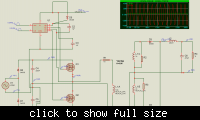
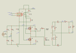
This is the simulation for the circuit. It does not work when I put capacitor series with the transformer.
 

Attachments

  • Untitled.png
    Untitled.png
    209.3 KB · Views: 159
Last edited:

Yes the capacitor i mentioned is Cs,

The fuse in series of primary winding on one side, this is just for the safety of MOSFETs in case any shortcircuit happens,
There is one more tip for u in this respect, instead of this fuse use a 60W filament tungsten bulb in series of primary winding. If the filament does not produce even very dim light when the transformer is oscillating it means that the current is in limit and ur turns need no change. (This bulb will be a safety instead of fuse as well as the replacement for ur Ammeter.)

Your calculation for number of turns is Ok, but the computer supplies are always rated upto 250V rms and they use 38 turns. So i recommend u 38. and for that volts per turn comes out to be 170/38 = 4.5 which is very logical and in safe limit.

And for simulation, first of all keep in mind that ur circuit will run in reality without Cs and without any problem. Coz the end of primary winding is attached to the center of the series of two capacitors C1 and C2 which give u the required voltage drop (Half the total DC voltage). Cs is an additional safety for the capacitors C1 and C2. Coz C1 and C2 are electrolytic DC capacitors and AC pulses can cause them a damage. And if ur simulation does not work with Cs in series that may be the limitation of the software. Just simulate it without Cs coz thats also fine.

220uF will be enough value for C1 and C2.

You have to use a MOSFET driver as in simulation to drive the High side MOSFET. PIC an be good controller if u r required to do that. Or simply SG3524 or SG3525 can be used.
 
Thanks ahsanfarooq. I'll try to get the bulb or fuse to test the transformer. For testing the transformer,can I directly use source with high frequency as input and test the current at the output or I need to do the mosfet switching too? As for the size of the copper, it is up to me whether how much current I'm drawing right.

Yea, the simulation can be done perfectly without the Cs. Thank you very much.

Actually, after my half bridge conveter, there is another circuit join to it. The 24VDC output of the half bridge will be the input for my DC-DC converter. Therefore, I'll be having 4 mosfets; 2 for half bridge and another 2 for DC-DC converter. I would like to ask if I'm using PIC, do I still need mosfet drivers connect to PIC? Or just only PIC will do? There is another thing that is since you suggested I use 30k Hz for my half bridge mosfet switching, can I use 20k Hz mosfet switching for my DC-DC converter?
 

First of all to test transformer u have to check the current of primary nt secondry. And without Any load on secondry. If the turns are mistuned then losses in core will draw unwanted current. That u have to check. Secondly how can u oscillate ur transformer without the mosfet?

Pic will give u the signal only and don't have strength and voltage enough to drive MOSFET and secondly the high side MOSFET will be at abt 300 volts so how can u drive it without a MOSFET driver.

And as far as the frequency is concerned, do u want to get drive of both circuits MOSFETs with same pic controler? If yes then u should knw that if that controler can handle it or nt. Once I tried to get 30khz and 50hz signal from same pic controler but I notice sm noise of 50hz in high frequency and dropped the idea....
 
hi
hello
i think that is a half-bridge converter circuit
 

Sorry there had been a mistake by me as i overlooked one thing in ur circuit which i noticed after the reply from above person. The mains is ractified in a way to get both capacitors C1 and C2 charged at full voltage ie 340V each. So the total voltage will be 680V. and half of it will drop across Cs and hence 340V on winding. So the number of turns for primary will be 38*2 = 76 in this case. And Cs should be rated for 400V AC. No change in number of turns for secondry if u have already calculated. I hope u got it now....
 
Can I ask CandleCookie what they are are actually trying to achieve. Perhaps an outline specification?

I get slightly worried when people pick a topology without knowing what it is and then appear to give figures based on RMS values and then start talking about PIC processors.

The most I have so far is that..

Offline AC/DC converter
Vline 240V RMS
Vout 24V DC
Pout 360 Watts

Genome

Edit

I'll get myself in trouble now.

My lecturer gave me a sample of transformer. It is the same type as shown in the website. | Transformers | Transformers | Transformers and Ferrite Kits & Cores | High Frequency Kits & Cores The winding should be done at the centre. The problem is how to differentiate primary and secondary?

I might suggest I live in fear of situations such as this. Assuming this is some sort of 'final year project' and it was your lecturer who suggested the Half-Bridge circuit with a voltage doubler input running from 240V RMS then I might guess that either he is trying to 'test you', because it was in your lecture notes and he knows it already or he is just not very good at his job and neither were his lecture notes....

Perhaps he enjoys killing his students.

Switch Mode Power Supply Design is not trivial and becomes less so when you move to the indicated power levels and start working with mains voltages. This is not an insult to you but from your previous postings you do not have the level of knowledge or experience required to cope with this project and, if the information you have been given by your lecturer to date is as indicated in your posts he should not be teaching or dealing with the subject.

Genome.. Again
 
Last edited:

Hi, ahsanfarooq. Yes, it is half bridge converter and total voltage is 680V if adding C1 and C2. But then during positive cycle, only C1 will be charged up. Therefore the voltage is 340V. After across the Cs, the voltage should be 170V. I thought this is the way. It is wrong?

Hi, genomerics. Thanks for your worries. Actually I'm trying to do a battery charger with the combination of half bridge converter and dc dc converter. My input for half bridge is 240Vrms and output of half bridge is 24Vdc. I don't think the power is 360W. Power is 36W as in 1.5x24=36W.
Assuming this is some sort of 'final year project' and it was your lecturer who suggested the Half-Bridge circuit with a voltage doubler input running from 240V RMS then I might guess that either he is trying to 'test you', because it was in your lecture notes and he knows it already or he is just not very good at his job and neither were his lecture notes....
Sorry, actually I'm the one borrowing the transformer from him. That transformer is just for my reference and it was used by his previous student. This is because I have no ideas what kind of transformer I should use. Is there anything wrong? Can you give me some ideas? I don't really understand. Is it any transformer will do?
 
Last edited:

My fault, I should have read through the thread more carefully. I had made an assumption that since you were looking at a half bridge that your power levels were relatively high. Since you are only looking for about 36W, let's call it 50W then this should be possible to do either with a single switch or two switch flyback or forward converter.

On the subject of the voltage doubler input as suggested this is usually used in circuits to allow dual voltage use. 110V/240V by moving a jumper,


The one on the left is a full-wave rectifier which would be used for 240VAC the one on the right is the voltage-doubler which would be used for 110VAC. The resistors balance voltage across the capacitors without dissipating excessive power. The capacitors themselves need only be rated at 200V. Assuming a peak of 260VAC input you will get about 370VDC at the output. If you were to use the doubler then that would be 740V. In your case you really need the full-wave circuit so 370V becomes your design figure.

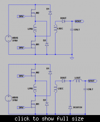
For Single Switch Flyback and Forward your basic converter power stages would look as shown next,


Hopefully I have the windings phased correctly. In both cases I have used clamp windings to allow for transformer reset. That means that M1 will be seeing peak drain excursions to 2 times VBUS or 740V and you would have to use 800V devices which may or may not be scary. It is possible to use other reset methods to reduce this but the gains might not be too large. You'll see the Flyback differs from Forward in terms of the way windings are phased and it has no output inductor. It is nominally simpler and cheaper but suffers from its own headaches.

The Two Switch versions are shown next,


Transformer reset is now back to VBUS by D1 and D2. Generally in all cases the duty cycle is limited to 50% but that is certainly true for these ones. The advantage is that the devices never see more than VBUS so 400V rated devices can be used. Of course it is slightly more complicated because there is the added upper Mosfet and you have to provide drive to it. That might be achieved using one of the special IC's or a simple pulse transformer.

As suggested for the power levels you are looking at any of the above circuits should be sufficient. The single switch circuits might be avoided because of voltage stresses. It's not infeasible and if cost was an issue then they might be preferred but in many cases the design whilst visibly simpler might be more complex. As a result I would recommend one of the second two..

Regarding your transformer, having read back through the thread, without doing some sums I would tentatively suggest that it might be too small. The main reason is that since you are implementing an offline converter there will be agency requirements for isolation, creepage and clearance between the primary and secondary windings. That can be anything up to 8mm or 4mm per side. You might be able to get away with 6mm or 3mm per side depending on the requirements in your country. The winding width of the bobbin is 16.4mm so that would only leave you with 10mm in which to fit the windings. As I say it is something that needs to be thought about but hopefully, if necessary, you will be able to obtain a different device.

Let me know if the above makes sense and then we can continue.

Genome.
 
Thanks Genomerics. I'm using the second two which you suggested.
The one on the left is a full-wave rectifier which would be used for 240VAC the one on the right is the voltage-doubler which would be used for 110VAC. The resistors balance voltage across the capacitors without dissipating excessive power. The capacitors themselves need only be rated at 200V. Assuming a peak of 260VAC input you will get about 370VDC at the output. If you were to use the doubler then that would be 740V.
So, the right figure is a voltage doubler and this causes the input of my transformer is 740Vdc and not 370Vdc.

In your case you really need the full-wave circuit so 370V becomes your design figure.
In order to get a 370Vdc, I need to use full wave which means additional two diodes at the front side? But as been mentioned by ahsanfarooq, the additional capacitor Cs will make the input voltage to be half. If my input source is 240Vrms, due to voltage doubler, the voltage will be 740V but since additional Cs, there will be voltage drop. Thus, the input of the transformer is 370V. Is it correct?

I had attached my simulation circuit. I had found out that the input voltage transformer is quite small. Is there any mistakes in the circuit? By the way, my mosfets already have internal diodes. Do I still need to add diodes at the mosfet?


Hi again.

You are still using the half-bridge circuit which is fundamentally different from the Two Switch Flyback and Forward converters I posted earlier.

Gong back to your input supply and the rectifiers. If you used one of the circuits I have suggested then you would not need two capacitors. For the half bridge you would because the transformer primary is returned to that 'soft' centre-tap.

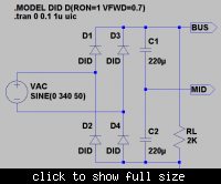
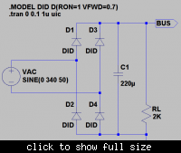
The circuit is


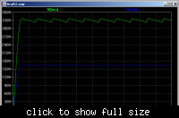
The output is


You can see that each capacitor charges up to half the peak mains input voltage, they behave as a voltage divider, and there is also ripple on the output due to the load RL.

If you use the Two Switch Flyback or Forward converter then you do not need that 'soft' centre-tap.

The circuit becomes,


The output becomes,


Look back carefully at the pictures of the Two Switch Topologies.

Your half-bridge has the upper Mosfet source connected to the lower Mosfet drain which are both connected to one side of your transformer primary, the other side going to the 'soft' centre-tap.

The Two Switch circuits have one side of the transformer primary connected to the lower Mosfet drain with the other side going to the upper Mosfet source. I hope you can see the difference. In these circuits the Mosfets are switched on together placing the primary across the input DC BUS.

Now look at the additional diodes. They are not connected across the same locations that you would expect to represent the Body-Source diodes of the Mosfets.

It's harder to explain for the Flyback circuit but the principle is the same. In the case of the Forward circuit consider that you have applied VBUS to the transformer primary for a period of time. The primary represents an inductor in the same way you are modelling it. It is referred to as the magnetising inductance.

Current in that inductor will ramp up to some value. This is called the magnetising current and is not coupled to the secondary. If it is not reset then when you turn the switches on again it will ramp up some more and that will continue until the transformer core saturates at which point things go bang!

You have to reset that current every switching cycle to avoid this happening. When the switches turn off the magnetising current will continue to flow and reverse the voltage across the transformer primary. The additional diodes, catch diodes, will clamp that voltage back across VBUS with the magnetising current ramping back down towards zero.

This is called transformer reset. If the setting volt-seconds are greater than the resetting volt-seconds then the core will still saturate. If they are less, or the same, then things will be OK. Since you are setting and re-setting through the same voltage, VBUS, then the times have to be the same. This is what enforces the 50% duty cycle limit in the case of such Two Switch converters.

Regarding your present model one problem you have is that you have made the winding inductances too low. If you refer to the following data sheet,

**broken link removed**

Then Page 2) includes the following table.


The Al value is the 'specific inductance per root turn' for the core set. Without actually determining an actual figure for the number of primary turns you will need suppose the result was 50. Then the magnetising inductance for N87 would be 2600E-9 x 50^2 or 6.5mH.

That would be the value you would use in your model for the primary and you would scale the secondaries accordingly.

On the subject of your half-bridge converter as I have said it is really for use at much higher power levels. There are also other problems with it that will make it less than ideal for your particular application. Although there are solutions one of the main problems is that you cannot reliably implement current mode control or current limiting to the circuit and would be forced to shut it off in such events.

To do so you might implement what is termed a flux balancing winding on the transformer but it is added complexity. The problem is that under current limit conditions the 'soft' centre of your input capacitor divider is driven in one direction by a charge imbalance between upper and lower switching cycles and ultimately the transformer core is driven into saturation.

In some respects that can be alleviated by the inclusion of a low value film capacitor in series with the primary but all that happens is that it rapidly takes up the offset and the converter ceases to function as well.

I'll leave things there because its quite a lot of extra information for you to read through.

Catch you later.

Genome.
 
Hi, Genome. Thanks for all the information.

On the subject of the voltage doubler input as suggested this is usually used in circuits to allow dual voltage use. 110V/240V by moving a jumper,
The one on the left is a full-wave rectifier which would be used for 240VAC the one on the right is the voltage-doubler which would be used for 110VAC. The resistors balance voltage across the capacitors without dissipating excessive power. The capacitors themselves need only be rated at 200V. Assuming a peak of 260VAC input you will get about 370VDC at the output. If you were to use the doubler then that would be 740V. In your case you really need the full-wave circuit so 370V becomes your design figure.
From this info, I understand that the output voltage for both circuit will be about the same if input is 240Vrms for full wave and 110Vrms for voltage doubler. Please correct me if I'm wrong.

Gong back to your input supply and the rectifiers. If you used one of the circuits I have suggested then you would not need two capacitors. For the half bridge you would because the transformer primary is returned to that 'soft' centre-tap.
If you use the Two Switch Flyback or Forward converter then you do not need that 'soft' centre-tap.
If I want to have a dual voltage use, is it alright for me to have two capacitors? According to the voltage doubler circuit, the -ve of the source is connected to the midpoint of the capacitor.

The Two Switch circuits have one side of the transformer primary connected to the lower Mosfet drain with the other side going to the upper Mosfet source. I hope you can see the difference. In these circuits the Mosfets are switched on together placing the primary across the input DC BUS.
By referring to the two switch 2nd circuit shown, the input of the transformer will be Vbus. Is it correct? But as for my case, the primary is connected to the source of upper Mosfet and midpoint of the capacitor. Therefore, the input voltage for the transformer is voltage across 1capacitor. Am I correct?

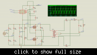
I have attached a new circuit by following the two switch 2nd circuit. But somehow it can't run at all. Do I miss anything? I just simply put the ratio of the transformer for this new circuit because I just wanted see whether this circuit can run or not.

Thanks for the transformer information. I keep on asking myself what is Al and how to use it. Now I know better.=)
 

Attachments

  • 1.png
    1.png
    221.6 KB · Views: 135

Hi, Genome. Thanks for all the information.


From this info, I understand that the output voltage for both circuit will be about the same if input is 240Vrms for full wave and 110Vrms for voltage doubler. Please correct me if I'm wrong.

That's correct.

If I want to have a dual voltage use, is it alright for me to have two capacitors? According to the voltage doubler circuit, the -ve of the source is connected to the midpoint of the capacitor.

Almost, but this type of Converter will always be connected across both capacitors. In this case the midpoint is not used by the converter. It allows the voltage double configuration.

By referring to the two switch 2nd circuit shown, the input of the transformer will be Vbus. Is it correct? But as for my case, the primary is connected to the source of upper Mosfet and midpoint of the capacitor. Therefore, the input voltage for the transformer is voltage across 1capacitor. Am I correct?

No as above the Converter is always connected across both capacitors. I'll show that later. Sorry, yes. In the half bridge circuit the transformer primary will only see the voltage across one capacitor or half the total.

I have attached a new circuit by following the two switch 2nd circuit. But somehow it can't run at all. Do I miss anything? I just simply put the ratio of the transformer for this new circuit because I just wanted see whether this circuit can run or not.

Your circuit is still not totally correctly drawn and you still need to correct a couple of other things. Almost there though.

Thanks for the transformer information. I keep on asking myself what is Al and how to use it. Now I know better.=)

Al comes from the equation for an inductor,

L = Uo.Ue.N^2.Ae/Le

Uo is the permeability of free space 4.pi.10E-7.
Ue is the effective permeability of the core.
Ae is the effective area of the core in metres^2.
Le is the effective length of the core in metres.

Those four parameters will be given in the core data sheet but because things 'vary' the manufacturer will quote 'effective' values and then give Al for a particular core where,

Al = Uo.Ue.Ae/Le

So

L = Al.N^2

Back to your circuit. This is the full power train,


On the left is your mains input at 240RMS the sine wave amplitude being 340V. This is followed by the rectifier bridge with things connected for full-wave operation. Next is the pair of filter capacitors, values to be determined based on hold up requirements. These have a pair of resistors across them to balance voltage against leakage currents.

Then we get to the Two Switch Forward Converter. I generally create circuits like this initially using ideal components and you might wish to do so as well. It 'simplifies' things and they can be made more complicated later. There are many times when you might try and fully model things all at once and it refuses to work. Then it becomes very difficult to work out where errors or problems might be.

As such my 'Mosfets' are modelled as ideal switches. The Spice definition is bottom right. In order to make them 'look' like Mosfets I have included Body-Source diodes as DS1 and DS2. If you were to use a more exact model then these would not be required. The reset diodes are DC1 and DC2.

In your present model you still have a 'short' between the upper Mosfet Source and the lower Mosfet Drain.

There is a current sense resistor, RPSNS, in the lower Mosfet Source. This will be used for protection, current limiting, and overall feedback control.

Next is the transformer primary. Your circuit is still showing a value that is too low. As discussed before I have 'guessed' at a value of 6.5mH. That can be adjusted later if needs be but, as long as it is 'near' then it will not affect circuit operation to any great extent.

Then we have the transformer secondary. Since this is what might be termed a 'single ended' converter with a maximum of 50% duty cycle we have to think a bit about its value. With a 24V output then the average input voltage needs to be, more or less, 24V as well. given the 50% duty cycle limit then that will mean the secondary winding has to present 48V to the input of the filter... 48V x 50% = 24V.

Then we look back at the primary and consider hold up times. Offline converters are generally designed to cope with a single cycle line drop out. During that time VBUS will fall. If we pick a minimum input voltage of 250V then that will be the primary voltage at this time. That gives us the transformer turns ratio as 250/48 or 5.2 and the secondary inductance will be
Lp/N^2 or 240uH.

I have set the coupling coefficient, K, to one.

Again since this is a 'single ended' converter you'll notice that it is not using the centre tapped full wave rectifier you have in your original ciruit. Power is only delivered during the primary side switch on time so you just have a single winding followed by the rectifier diode DREC. During switch off time the output inductor LFILT circulates through DCATCH.

Finally there is the output filter capacitor, CFILT, with nominal ESR, RESR and the load, RLOAD, set to 12R to draw a nominal 2A of output current.

You might wish to start a new circuit and try to redraw what I have given here using the ideal components if you can find them in your version of Spice. Let me know how things are so far and, if it is good, then next I'll add in the basic control circuits and we can begin regulating some output voltage and look at the waveforms.

It's not really worth trying to run an analysis until the complete circuit is in
place and ready to go.

Genome.
 
Last edited:
Hi, Genome. I would like to ask for the pull power train circuit shown, the transformer is connected to the source of upper Mosfet and drain of lower Mosfet. The voltage input for the transformer is 340v? What is the use of the resistors 220k? Will they cause a lot of power loss because I'm making a battery charger.
I have followed the connection of the circuit. The circuit still can't run. But after I changed the transformer, the simulation can run but the result is not satisfying. I think the previous transformer is more suitable.


By the way, it is not necessary to have a mid-point transformer to obtain a 24V? This is because by referring to your circuit, the output of the transformer is 48V and at the output of half bridge, it becomes 24V.

For the RPSNS, instead of using resistor, can this be replaced by a diode? Since diode only allowed forward bias.
 
Last edited:

It seems we are getting there.

Regarding the 220K resistors. Electrolytic capacitors suffer from leakage currents. If there is a differential in that then you will end up with a voltage offset from the midpoint.. Actually, now you have forced me to think about it I might be able to argue a case for not having those resistors in place. Otherwise, for the moment, their dissipation works out to be about 0.25 Watts which is quite low.

Your circuit model is still not the same as the 'picture' I have given. Perhaps you might consider starting a 'new' one. Leave out U1 and go back to the 'coupled inductors' for your transformer.

As I have said what I am suggesting is a 'single ended' converter which only delivers power to the output during one particular phase of the switching cycle. The other is effectively redundant and a centre tapped secondary will not be able to utilise it.

RSNS is, or will, form part of your feedback loop in order to control the output voltage. A resistor will give you a predictable linear response to switch, primary side, current a diode would not.

Genome.
 
This is the latest circuit. I'm facing with the connection of the Mosfet driver. Initially the both Mosfets are connected together, so the Mosfet driver is used to drive the upper Mosfet by connecting the driver to the centre of Mosfets. But referring to the new circuit, both Mosfets are connected through primary transformer.

 
Last edited:
Sorry for the delay. The image server went down so I could not see your latest circuit. It's up again.

Looking good but one last mistake...


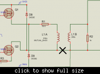
Ideally you should not need R1 so remove it and make the connection directly to the top of L1:A. You can also remove R2.

I'm uncertain as to how your 'transformer model' L1:A and L1:B is specified in the software you are using but would expect that the MUTUAL statement defines the coupling and that should be set to 1.

There is also the question of how the windings are 'phased' but I suppose if they work out to be the wrong way around you can always turn one of them around..

To see if things work then instead of using the previous U1 hopefully you can find some voltage sources. Again this is my unfamiliarity with your software but for both Mosfets add the following,


This is a pulsed voltage source with the duty cycle set to 0.37 and a period that will result in 100KHz operation. Hopefully if things are the right way up elsewhere you should be able to run it and see some things actually happening..

Fingers crossed anyway.

Let me know how it goes.

Genome.
 
Status
Not open for further replies.

Similar threads

Part and Inventory Search

Welcome to EDABoard.com

Sponsor

Back
Top