sysysy
Member level 3
hi,
below is the internal circuit of LM35, may i anyone can give me the details explanation regarding this circuit?
I wish to understand the circuit
There is some description for this circuit that i not really understand, i already copy and paste below.
why is the transistor use for? how it operate?
what is the op amp use for? amplifier or comparator?
Description:
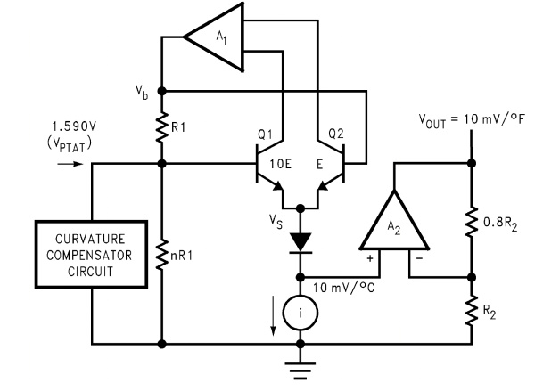
The circuit diagram is shown above. Briefly, there are two transistors in the center of the drawing. One has ten times the emitter area of the other. This means it has one tenth of the current density, since the same current is going through both transistors. This causes a voltage across the resistor R1 that is proportional to the absolute temperature, and is almost linear across the range we care about. The "almost" part is taken care of by a special circuit that straightens out the slightly curved graph of voltage versus temperature.
The amplifier at the top ensures that the voltage at the base of the left transistor (Q1) is proportional to absolute temperature (PTAT) by comparing the output of the two transistors.
The amplifer at the right converts absolute temperature (measured in Kelvin) into either Fahrenheit or Celsius, depending on the part (LM34 or LM35). The little circle with the "i" in it is a constant current source circuit.
The two resistors are calibrated in the factory to produce a highly accurate temperature sensor.
The integrated circuit has many transistors in it -- two in the middle, some in each amplifier, some in the constant current source, and some in the curvature compensation circuit. All of that is fit into the tiny package with three leads.
<end>
Thanks.
below is the internal circuit of LM35, may i anyone can give me the details explanation regarding this circuit?
I wish to understand the circuit
There is some description for this circuit that i not really understand, i already copy and paste below.
why is the transistor use for? how it operate?
what is the op amp use for? amplifier or comparator?
Description:
The circuit diagram is shown above. Briefly, there are two transistors in the center of the drawing. One has ten times the emitter area of the other. This means it has one tenth of the current density, since the same current is going through both transistors. This causes a voltage across the resistor R1 that is proportional to the absolute temperature, and is almost linear across the range we care about. The "almost" part is taken care of by a special circuit that straightens out the slightly curved graph of voltage versus temperature.
The amplifier at the top ensures that the voltage at the base of the left transistor (Q1) is proportional to absolute temperature (PTAT) by comparing the output of the two transistors.
The amplifer at the right converts absolute temperature (measured in Kelvin) into either Fahrenheit or Celsius, depending on the part (LM34 or LM35). The little circle with the "i" in it is a constant current source circuit.
The two resistors are calibrated in the factory to produce a highly accurate temperature sensor.
The integrated circuit has many transistors in it -- two in the middle, some in each amplifier, some in the constant current source, and some in the curvature compensation circuit. All of that is fit into the tiny package with three leads.
<end>
Thanks.