Continue to Site

Welcome to EDAboard.com

Welcome to our site! EDAboard.com is an international Electronics Discussion Forum focused on EDA software, circuits, schematics, books, theory, papers, asic, pld, 8051, DSP, Network, RF, Analog Design, PCB, Service Manuals... and a whole lot more! To participate you need to register. Registration is free. Click here to register now.

crystal oscillator help needed!

Status
Not open for further replies.

somenick

Newbie level 6
Joined
Dec 8, 2010
Messages
11
Helped
0
Reputation
0
Reaction score
0
Trophy points
1,281
Activity points
1,406
Hello everyone, I could use some help building a circuit to provide
a 6MHz clock signal! I stumbled upon a page which showed a rather
sweet looking circuit:

(The circuit will be posted as soon as the forums let me post a picture.. *sigh*)

I'd like to try and build this, since i've got a stockpile of them (the 74LS00's, that is)!

My question is how to convert this circuit to 6MHz? Do I need to change
the capacitor/resistor values? Or simply put a 6MHz crystal and it'll run?

Thanks in advance!

---------- Post added at 17:04 ---------- Previous post was at 17:04 ----------
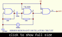
(The circuit will be posted as soon as the forums let me post a picture.. *sigh*)


there it is!
 
Last edited:

It should work at 6 MHz and possibly even somewhat above 6 and below 4. In any case, the circuit is very simple, so the best thing is: hands-on, try it yourself!! :)
 
It should work at 6 MHz and possibly even somewhat above 6 and below 4. In any case, the circuit is very simple, so the best thing is: hands-on, try it yourself!! :)

I do not mean to be harsh, on the contrary! Though, you DO realize that you did
not answer the question at hand, I hope.. I will interpret your answer as "Yeah,
just change the crystal and it should work (in the region of 4-6MHz)", taking it
one step further and adding "The values of the resistors and the capacitor do
not alter the output frequency"

I really have considered your "hands-on" approach, but I don't have any kind
of instrument that can measure frequencies of 6MHz. Were that the case, I'd
probably have answered the question myself.

Thank you for your time nevertheless, but since I don't consider my question
answered if anyone has anything to add, it would be welcome!
 

Were that the case, I'd

Ehm... good point. Yes, you are right saying that your question wasn't answered.

Values of capacitors and resistances DO have an effect on the circuit's behaviour. Resistors are used to give feedback to the NAND gates used as inverters, so I reckon that their value is more related with the IC than with the crystal. 100 nF capacitors seems a DC decoupler between 1st and 2nd gate, so it is not critical. The 120 pF capacitor allows you to "detune" the crystal so that you can slightly adjust its working frequency. You can replace it with a varicap if you want.

All of that said, I don't see any reason why the circuit shouldn't work @ 6 MHz. Let me say that I am pretty sure! :wink:
 
Most crystals can only be changed from their labelled frequency by a small amount, for 6Mhz this would be +-200 hz or so. Within this range the crystal can be represented by its ESR, equivalent series resistance, in thr region of 10 -100 ohms. At a lower frequency, its the ESR +.01 pF capacitor, higher, ESR + 10mH. If your oscillator can cope with these values, it would still oscillate (but not the one shown :) ).
Frank
 
Verified working, thank you guys!
 

verified working by doing...? Changing the crystal or adjusting some component values? This information will help others in the future.
Thanks.
 

Hi, there is nothing complicated - if you need 6Mhz, just replace XTAL. You need 6.000MHz, then you have to play around 120pF capacitor
 

Status
Not open for further replies.

Similar threads

Part and Inventory Search

Welcome to EDABoard.com

Sponsor

Back
Top