Continue to Site

Welcome to EDAboard.com

Welcome to our site! EDAboard.com is an international Electronics Discussion Forum focused on EDA software, circuits, schematics, books, theory, papers, asic, pld, 8051, DSP, Network, RF, Analog Design, PCB, Service Manuals... and a whole lot more! To participate you need to register. Registration is free. Click here to register now.

Inductance of an Air Core Coil

Status
Not open for further replies.

MrElec

Advanced Member level 4
Joined
Oct 10, 2005
Messages
108
Helped
10
Reputation
20
Reaction score
9
Trophy points
1,298
Location
Tunisia
Activity points
2,040
Hi,

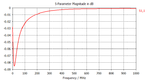
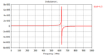
I've simulated an Air Core Coil with CST MWS and i want to get its characteristics L inductance and Q quality factor by using S-parameters from full-wave simulation,knowing that my frequency range extends from 10 MHz to 1000 MHz.
 

In ADS, you can convert S-params to Spice model for simulation.
Also, there are several threads in this forum just sevral days ago to discuss how to calculate L and Q from S-param or Y-param.
 
  • Like
Reactions: MrElec

    MrElec

    Points: 2
    Helpful Answer Positive Rating
Be aware that when using full wave solvers that S, Y, and Z assume different terminations! S parameters assume terminated impedances of all other ports and therefore will look capacitive for inductance caluculations, Y assumes a short which of course is desired, and Z assumes that all other ports are open...strongly capacitive!!
 
Thank you for the help but i still confused about extracting the inductance value of a simple air coil (see the photo) from S-parameters of full wave simulation, i've found this link:

The Designer's Guide Community Forum - Inductance extraction: L reduce with frequency?
Air coil.png

These are my results: S-params and Inductance value calculated by CST macro (i don't know the used model ):
 

Attachments

  • S-params.png
    S-params.png
    8.3 KB · Views: 261
  • L.png
    L.png
    9.2 KB · Views: 278

A couple of things here to be aware of... First since you are using a single port, S parameters can be fine since you can access the Z matrix in the circuit solver via the S Parameters and the known reference. The thing you have to be careful of is this...a inductive coil looks like a short if you look at the S parameters. S parameters were set up to give a lot of information of a structure near regions where the impedance is well matched to the reference. In this case the match is very poor, and convergence in your full wave solver may be difficult. If possible track the inductance itself from within the full wave solver and improve the mesh until the inductance no longer changes. Also, it seems that your coil has a self resonance ~600MHz above which it appears "Capacitive". I would make good efforts of convergence of the mesh, HFSS is great for these models as I can define my inductance and Q and have HFSS run automatically to converge my mesh to these quatities rather than just S Parameters (which are near useless this far away from self resonance)

have fun :)
 
Hello,

In fact i'm trying to build my own air coil inductors with high values from 300 to 400 nH by wire winding, and to ensure that the coils inductances are as fabricated , i must compare between the values of inductances found by formulas and those extracted from full wave simulation by CST.

1-
If possible track the inductance itself from within the full wave solver and improve the mesh until the inductance no longer changes

Could you please explain more: " track.. from within.."


2-
HFSS is great for these models as I can define my inductance and Q and have HFSS run automatically to converge my mesh to these quatities rather than just S Parameters

What do you mean by define the inductance and the Quality factor and have HFSS run... (do you give HFSS these values in advance? really i didn't understand this)

I've drawn a coil with HFSS, and imitated the given steps given by Shlomo22 (step 6) :

https://www.edaboard.com/threads/162347/

but i'm not sure if my design is correct and of course the results.

Can you give me some help (Steps to take in HFSS) and thank you.
 

Attachments

  • Coil Inductor.rar
    24.6 KB · Views: 166
Last edited:

OK, Merry Christmas...I have attached a correctly setup project to determine the inductance of the given coil as a function of frequency. I have setup the project to converge to the inductance of the coil, which I determine from HFSS without a circuit tool, to within 2%.

The self resonance is ~810MHz. The inductance @ 200MHz is 160nH and 500MHz is 232nH.

Also, be wary of "formulas" for inductance. Most of them assume DC and are only valid at frequencies << the self resonant frequency of the coil. Also, if you go to very low frequency, ie kHz, you will need to solve inside the metal as the Q will have strong contributions from both the AC and the equivalent "DC" loss mechanisms of the wire.


Have Fun :)
 

Attachments

  • Coil Inductor_TALLFACE.zip
    34.2 KB · Views: 192
  • Like
Reactions: MrElec

    MrElec

    Points: 2
    Helpful Answer Positive Rating
I wish you a happy Christmas with plenty of gifts. The problem as you have said TALLFACE in your earlier posts is related to my poor meshing this is why i couldn't reach the desired results. I compared the mesh of your constructed coil (HFSS) with mine (CST) and i've noticed big difference between the two because i've duplicated my work from a CST presentation with no given information about mesh.
One least question please: how to compare between the S-params (S11 and S21) in the *.s2p file given by the coil constructor and those obtained by HFSS or CST?

Best regards.
 

Attachments

  • Inductor with CST.pdf
    116 KB · Views: 272

Status
Not open for further replies.

Part and Inventory Search

Welcome to EDABoard.com

Sponsor

Back
Top