Continue to Site

Welcome to EDAboard.com

Welcome to our site! EDAboard.com is an international Electronics Discussion Forum focused on EDA software, circuits, schematics, books, theory, papers, asic, pld, 8051, DSP, Network, RF, Analog Design, PCB, Service Manuals... and a whole lot more! To participate you need to register. Registration is free. Click here to register now.

Electronic Pulse changer Help & advice required please.

Status
Not open for further replies.
Hi,
Yeah the size of the item is the only concern, apparently its 105mm x 61mm before it's fitted into a box.

I've found more info, Everyday Practical Electronics done a construction project with exactly the same item back in September 2008, I managed to find the article & have it as a pdf, there is a parts list & all the operating & construction details etc, You can download the PCB print & PIC hex from the EPE website.

speedocorrector.jpg


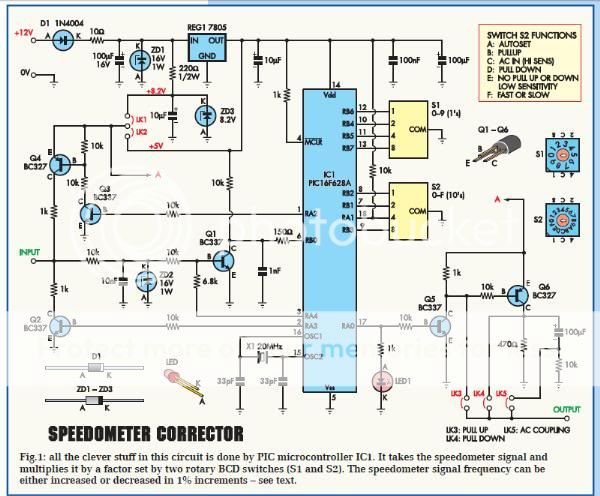
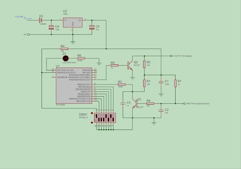
I'm wondering if it would be possible to shrink the size of the unit down a bit as there looks to be a lot of spare space on the PCB.


Cheers.
 

I don't like the grounding arrangement on the XTAL caps ! It is quite cheap for what you get though.

Brian.
 
  • Like
Reactions: jojoe

    jojoe

    Points: 2
    Helpful Answer Positive Rating
As you say, there is a lot of spare space - it could easily be shrunk down. You could make it very tiny if you went surface mount. Also, if you did your own PCB you could leave off the switches & simply hard wire the correct code. I reckon it wouldn't be too difficult to build one onto Veroboard (through hole - not surface mount).

Keith.
 
  • Like
Reactions: jojoe

    jojoe

    Points: 2
    Helpful Answer Positive Rating
I don't like the grounding arrangement on the XTAL caps ! It is quite cheap for what you get though.

Brian.

Hi,
That's way over my head, I can't understand schematics, my knowledge of electronics is very very basic.


Cheers.
 

Quite a lot of that circuit is to make it general purpose, it has programmable pull-up or pull-down and the output pulse voltage can be either 5V or 12V. If you are using a Hall effect sensor you don't need any of that. More modern PICs have built in oscillators too so you could eliminate the crystal and loading caps as well.

I think Keith probably spotted the XTAL caps problem too. It isn't technically wrong but good practice is to keep the wiring to the crystal and the two capacitors as short as possible. On that board the tracks are far too long and even jump from side to side of the board.

Using the pulse swallowing idea, if the error is acceptable, I reckon (without actually trying it) I could build that in one 8-pin IC with just a few resistors, capacitors and a Zener diode.

Brian.
 
  • Like
Reactions: jojoe

    jojoe

    Points: 2
    Helpful Answer Positive Rating
Yes, I saw the crystal ground - you follow it round wondering if it is ever going to reach the PIC ground pin. It reminds me of AB Electronics, but that's another story.

I think we will need to come up with a circuit to do it. I am tied up for the next week (got to do some work & go away) but I can have a look when I get back if it isn't sorted by then.

Keith
 
  • Like
Reactions: jojoe

    jojoe

    Points: 2
    Helpful Answer Positive Rating
"AB Electronics" - tell me more.....

I'll assume the Hall device has TTL level outputs and have a bash at using a 10F202 (because I've got them in stock) and see what I can come up with. My first scribbled design has 6 components !
Hold on Jojoe, we're coming to the rescue....

Brian.
 
  • Like
Reactions: jojoe

    jojoe

    Points: 2
    Helpful Answer Positive Rating
Hi,
I don't expect you guys to get wrapped up in this project just for me, especially at this time of the year when everyone has lots to do etc.

It was probably quite naive of me to think that it would just be a case of placing a PIC chip in line to do the km/h to mph conversion, even if it were that simple I wouldn't have a clue of how to write a code for the PIC.

The speedo corrector that I posted details of is good in as much as it allows a lot of adjustment, this is very handy to anyone who has a motorbike & wants to change the sprocket gearing. Most bike speedos are driven via the gearbox so changing the sprocket gearing will cause the speedo to be out, this is quite a problem for most owners & there are devices on the market for this reason, one such device is called "Speedo Healer"

With hindsight a device that has adjustment rather than a fixed device would be a lot more beneficial.

I don't know if this will help but I found the circuit below on the internet.

The guy has built it himself & he says that he will give anyone that wants it the hex code he has used for the PIC.
He has tested it on the Honda (Firestorm) speedo & a Yamaha R6 speedo, my bike is a Yamaha so I would imagine it would be compatible.

Here's the link to the topic:

**broken link removed**


simple11.jpg


Cheers.
 

That is useful because it shows us the polarity and voltage of the sensor. I was going to make it selectable with a switch but now that isn't necessary. Give us a day or two and I think we can come up with an even simpler and cheaper solution.

Brian.
 
  • Like
Reactions: jojoe

    jojoe

    Points: 2
    Helpful Answer Positive Rating
Hi,
thank you very much for your help, that really is very nice of you :)

There is no immediate rush for a device as the bike won't be hitting the road until the spring so please don't put yourselves out.

I just wish I could be more helpful with this project but as I've mentioned electronics isn't really my thing (I'm more mechanically minded), I would love to have a better understanding of electronics, it's just getting the time to study up on the subject.


Cheers.
 

I've already got a prototype running in simulation, it has a switch (if you want to fit it) to convert to MPH or leave it as it is in KPH and a switch (again if you need it, otherwise leave it out) to give low accuracy (~5%) or high accuracy (~0.02%) conversion. It works in low resolution but I haven't debugged it for high resolution yet. The reason for two resolutions is that depending on how your existing speedometer averages it's reading, the high res version might give a 'jumpy' reading, you will have to try it to find out. It has only 8 components and a build cost of about 1 pound !

Brian.
 
  • Like
Reactions: jojoe

    jojoe

    Points: 2
    Helpful Answer Positive Rating
Hi,
well you don't hang about do you :grin:

Yeah I'll fit the MPH switch & having the option of low or high resolution seems a good idea.
I'll certainly have a go at building the device, I have quite a few components lying around on old circuit boards from old TV's House alarms etc so I may already have a some of the components that are needed (nothing gets thrown out in this house :lol: ) I also have some matrix board & breadboard.

The only problem is that I won't be able to test the device on the bike out on the road as it's off the road until the spring. I can hook up the device on the bike & try it stationary.
The bike doesn't have a rev counter which is a shame or I would have been able to note the displayed km/h speed at given revs and then tried the mph speed at the same revs to see if it worked out.

Could I be so bold to ask if the finished device could be made to incorporate an adjustable correction value to accommodate different sprocket gear ratios as this would be very handy indeed.

Also .... I have contacted the lad that built the "DIY Speedo Healer" that I posted the circuit diagram of in post #28 & he has given me the Hex for the PIC & the source code.


Many thanks, Joe.
 

Unfortunately, I can't add an adjustment to the IC and software I've written. The reason is simple, the microprocessor only has 6 pins, with supply and ground, in and out and the two switches they are all used up.

What I actually done should be 'universal' anyway, rather than count sprockets and gears, I have simply divided the number of pulses entering the IC by omitting some as they leave it. In low accuracy mode it drops 3 pulses in every 8 giving a conversion factor of 5/8 or 0.625 (1.600 Km to the mile or about 0.6% out), in high accuracy mode it drops 39 pulses in every 103 giving a factor of 64/103 or 0.61235 (1.6094 Km to the mile or about 0.002% out). I have spaced the missing pulses out as evenly as possible so the existing speedometer shouldn't see the gaps which would result in the reading jumping up and down. The beauty of doing it this way is it doesn't matter what the original pulse timing is, it makes the conversion appear invisible to the existing unit, the slower pulse rate just makes it think you are traveling slower so it gives a lower reading. It also means that the odometer also measures in miles instead of Km which will work with the trip meter but unless you know of a way to reset the overall distance will I'm afraid, muck up your total distance measurement. It will still have the original Km reading with the new miles added to it. It works in a simulator but I haven't had time to build it and test it electrically.
What I'm going to do is feed it from a signal generator and monitor the output on a frequency counter. In theory, if I dial in a frequency equal to a speed in Km/h it should read on the counter in it's equivalent MPH value. For example I feed 160.09 Hz in and get 100Hz out.

Brian.
 
Hopefully, the existing unit already has some integrating and averaging built in to smooth out the slow-speed pulse erratics.
 
  • Like
Reactions: jojoe

    jojoe

    Points: 2
    Helpful Answer Positive Rating
Hi,
WOW....that sounds great Brian, & as KJ6EAD says maybe the unit already has something to smooth out the slow speed pulses, I imagine it would have some built in tolerance for this.

....Unfortunately, I can't add an adjustment to the IC and software I've written. The reason is simple, the microprocessor only has 6 pins, with supply and ground, in and out and the two switches they are all used up
I'll live without the adjustment, the main thing is that the speed display will be in mph instead of km/h so I don’t have to ride along doing maths!
Adjustment may never be needed anyway as I may always use the standard size sprockets.


....It also means that the odometer also measures in miles instead of Km which will work with the trip meter but unless you know of a way to reset the overall distance will I'm afraid, muck up your total distance measurement. It will still have the original Km reading with the new miles added to it.
That doesn’t matter at all, I’ll keep a record of when the device was fitted so I’ll be able to work out the true recorded mileage.


....What I'm going to do is feed it from a signal generator and monitor the output on a frequency counter. In theory, if I dial in a frequency equal to a speed in Km/h it should read on the counter in it's equivalent MPH value. For example I feed 160.09 Hz in and get 100Hz out.
I see your thinking behind that, hopefully it will give the desired result.


Many thanks, Joe.
 

Sorry for the delay, I built it and it wasn't accurate. After much head scratching I discovered my expensive HP signal generator isn't producing the frequency on it's display (aaarrggghhh!!!). It is out by about 20Hz which at the frequency I was using amounts to about 5% error so you can see why using it to verify a math calculation caused such a headache.
Anyway, the circuit works as it should and the output is as accurate as predicted. The only caveat is that it does have a maximum speed limit, it will become inaccurate if you exceed 615 MPH but I think you would have other worries if you reached that anyway!

The attached pictures show the input pulses in the top row, the output in high resolution mode in the middle and low resolution at the bottom. The algorithm is to drop (not pass through) 3 in every 8 pulses for low res and 39 in every 103 in high res mode.

In high res, a speed of 1.609 KMH gives an output of 1.001 MPH so it's not far off the mark. It uses 6 components in total.

Send me a PM so I can send you the details.

Brian.
 

Attachments

  • in_hi_lo.jpg
    in_hi_lo.jpg
    16.5 KB · Views: 84
Last edited:
Hi,
Absolutely no need to apologise for any delay, I wasn't expecting as much help as I've already received so I'm grateful for any efforts, sorry for the headache :smile:

I never doubted for a minute that the circuit wouldn't work and be as accurate as you thought it would be :wink:....accurate to 615mph, glad you built in a little extra tolerance :-o

6 components sounds just like my kind of circuit .....I'll get the soldering iron warmed up then.....


I have just tried to send a PM but when I click the PM button I get a message saying that I can't send you one as you have chosen not to receive PM's, do you have to change a setting to receive them?


Cheers.
 

Sorry about the PM, I forgot I had turned it off. Too many "Drive by" messages!
I have sent a PM to you with instructions on how to contact me.

Brian.
 
Hi Brian,
Ok I have contacted you as per the PM.

Thank you for your help & kindness it's very appreciated.

We have a Maplins local to us so getting the other parts shouldn't be a problem, that's if I haven't already got the parts in my inventory of old circuit boards to cannibalise!


Great website by the way.


Many thanks for all of your help.

Regards, Joe.
 

Hi everyone & Happy Christmas to you :grin:

Just to let anyone reading the thread know.....

I contacted Brian & he very kindly sent me the programmed IC & construction details of the circuit, I made up the circuit & tried it connected up to the bike, I'm very glad to tell you that it works.

As the bike isn't on the road I can't test it in motion but for a rough test I adjusted the engine tick over to a fast setting & with top gear selected the speedo was showing a reasonably steady 50 km/h, there was a little bit of fluctuating now & then (48 - 52 km/h) probably due to there being no load on the transmission.

I then fitted the converter set to the high res setting, the speedo reading was noticeably fluctuating quite a bit more, between 26 - 36 mph, Brian did mention that the high res setting may give a jumpy reading so I switched it to low res which gave a much more stable reading with the fluctuations being on par with the original set up before the converter was fitted, so I think it's safe to say that the converter is working just how Brian thought it would :grin:

I have to say a massive Thank You to Brian, without who's help I wouldn't have been able to make the converter, Thank you Brian :wink:

Best wishes to all for 2011.

Regards, Joe.
 
  • Like
Reactions: KJ6EAD

    KJ6EAD

    Points: 2
    Helpful Answer Positive Rating
Status
Not open for further replies.

Part and Inventory Search

Welcome to EDABoard.com

Sponsor

Back
Top