Continue to Site

Welcome to EDAboard.com

Welcome to our site! EDAboard.com is an international Electronics Discussion Forum focused on EDA software, circuits, schematics, books, theory, papers, asic, pld, 8051, DSP, Network, RF, Analog Design, PCB, Service Manuals... and a whole lot more! To participate you need to register. Registration is free. Click here to register now.

Electronic Pulse changer Help & advice required please.

Status
Not open for further replies.

jojoe

Member level 1
Joined
Jun 30, 2009
Messages
38
Helped
1
Reputation
2
Reaction score
1
Trophy points
1,288
Location
UK
Activity points
1,669
Hi,
I'm hoping someone can advise me what the simplest way would be to build a small device to reduce electronic pulses by a given amount.

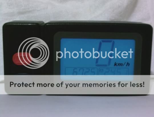
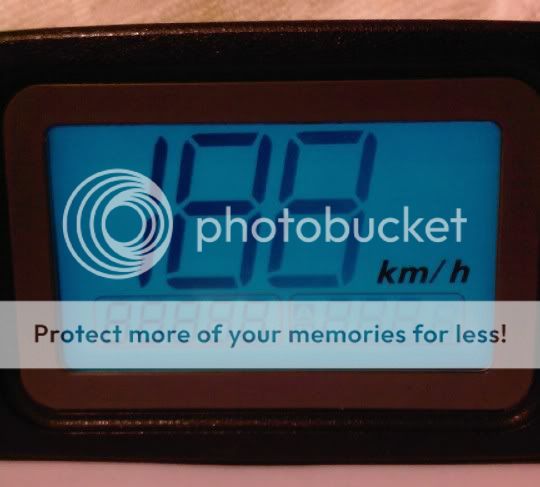
The device is for a digital motorbike speedometer that currently reads in km/h which I wish to convert to read in mph.

The speedometer displays the speed via pulses that is sent to it, if these pulses were reduced by the correct amount the speedometer would display in mph.
I believe that every pulse it receives will need to be reduced to 0.6213711 of a pulse.

1 / 1.609344 = 0.6213711 (1.609344 is the km/h to mph conversion)

Example:

100km / 1.609344 = 62.137119 mph


Any advice appreciated.

Thanks.
 

Most digital speedometer/odometer systems have a method for calibration built in to accomodate different tire and wheel sizes. You just have to read the manual to find the method. If you calibrate for MPH, it will read in MPH, even if the indicator says KPH.
 
  • Like
Reactions: jojoe

    jojoe

    Points: 2
    Helpful Answer Positive Rating
Hi,
Thanks for the reply, unfortunately the system fitted has no such system.

The pulses come from a Hall effect sensor that is mounted on the output shaft of the gearbox (where the front sprocket is mounted)
Changing the wheel size, or changing the size of the drive sprockets size will make the speedo give an inaccurate reading, however that isn't a cause for concern at the moment.

What I require is a way to change the pulses received by the speedo head, I imagine that this could be done wit a pic chip that is programed to reduce the pulse count like described in my first post.


Cheers.
 

You can reproduce an adjusted pulse rate but before looking at that option, where do the existing pulses go? If they are only being used to drive an analog tachometer, it would be much easier to amplify/attenuate the meter voltage than modify the pulse rate. If the pulses must remain digital, the two simplest options would be to use a PLL to lock a new pulse generator to a fraction of the present one, or to count the pulse rate, do some math to make the conversion then synthesize a new pulse rate.

What exactly is the application?

Brian.
 
  • Like
Reactions: jojoe

    jojoe

    Points: 2
    Helpful Answer Positive Rating
Hi,
the existing pulses from the Hall effect sensor go directly to the digital speedometer, this is a sealed unit and I could only gain access to the inside of it by cutting it open, obviously I don't want to do that.

There is no analog tachometer.

I don't know how many pulses the speedometer receives for a given speed, but obviously the more it receives the faster the digital display reads, if the pulses are reduced across the board by the ratio mentioned above then the reading will be in mph.


Cheers.
 

Assuming the gearbox is not running at super high speed and it may actually be running slowly:

1. You can "pulse swallow", in which you sense and recreate every pulse except enough to drop the rate down. For example, a rough calculation would be to drop the rate by 40% so you drop two pulses in every 5. This may be acceptable if you can live with that accuracy, it amounts to about 2% error but has the drawback that the missing pulses may cause a jitter in the reading. You can make it more accurate by increasing the number of pulses while holding the ratio of drops the same but this may make it wildly inaccurate at very slow speeds.

2. You can do it in software by using a microprocessor (perhaps even one as simple as the PIC10F202 which costs about 40p) as a frequency counter and as a timer to generate you converted pulse rate. You have to be careful using this method that you check for a stopped gearbox, without an input pulse it could continue to produce pulses based in the last pulse it tried to measure.

Brian.
 
Hi,
Thanks for the reply.

Just done a very rough calculation regarding the number of pulses:

The rolling circumference of the back wheel is somewhere around 2075mm
so 1km divided by this gives the number of rear wheel revolutions to cover 1km:

1km = 1,000,000 mm
1,000,000 / 2075 = 481.9

So the rear wheel turns approx 481.9 times per km travelled.


The rear sprocket has 44 teeth & the front 14 so that is a ratio of 3.14.
44 / 14 = 3.14

So the front sprocket will turn 3.14 times for 1 turn of the rear sprocket.

481.9 x 3.14 = 1513 front sprocket revolutions per km travelled.


The magnet that triggers the hall effect sensor is fitted to the front sprocket & has 4 fields, (North-South-North-South) so 4 pulses per revolution of the front sprocket.

1513 x 4 = 6052 pulses per km travelled

So travelling at 1km per hour there is approx 6052 pulses.

At 100kmh (approx 62mph) that's 605,200 pulses.


** I hope you follow all of that, do remember that the above is a very rough calculation.**


It may be a lot more complex than I thought, but I imagined this device to be a sort of frequency divider, simply reducing the pulses by a set amount ?


The type of device I need is already available to buy, it's a small device that is wired into the signal wire to the speedometer, I assume it reduces the pulses by the correct amount to make the speedometer display in mph.

Of course I could just buy one of these devices but I'm just interested to see if I could make one as a project, I have a pic programmer lying around somewhere, it would be nice to blow the dust off it & put it to work.


Cheers.
 

That's perfectly clear thanks.
The missing information is "what is it used for?" The answer makes a difference to the solution, for example in industrial control gearboxes there may be tons of engine mass to be controlled and momentary loss of tacho pulse may be acceptable. On the other hand, in a tiny gearbox in a hospital drip feed, it could be a matter of life and death. Based on the speeds and sizes you are mentioning, am I right in thinking this is speedometer/odometer for a bicycle?

Brian.
 
  • Like
Reactions: jojoe

    jojoe

    Points: 2
    Helpful Answer Positive Rating
See the first post - it is a motorbike speedometer.

Keith

---------- Post added at 12:17 ---------- Previous post was at 12:15 ----------

PS there was a very similar post a while back but I cannot remember the final solution and cannot find it. I like the pulse dropping idea though.

Keith
 
  • Like
Reactions: jojoe

    jojoe

    Points: 2
    Helpful Answer Positive Rating
Thanks Keith. I've been a preoccupied with being snowed in and not having any water, I should have re-read from the beginning for the information. The -17C weather you might have seen on the TV news was recorded close to here!

JoJoe, the problem with frequency division is the complexity of dealing with fractional amounts. It's easy when you divide by a multiple of 2, a bit more complicated when you divide by other integers and very difficult when you divide by floating point numbers. Measuring the input frequency or period is quite easy, doing mathematics on the result is also fairly easy but recreating a new pulse series based on the result and doing it all in real time is quite difficult.

There are ways of doing it though. Can you tell us the precision of your speedometer readout. How many digits and does it measure tenths of KPH as well? The reason I ask is that the algorithm is simpler when fewer digits are needed.

Brian.
 
  • Like
Reactions: jojoe

    jojoe

    Points: 2
    Helpful Answer Positive Rating
Five eights would be 0.58% error. That should be good enough and could be done by dropping 3 out of 8 pulses.

We have some snow here. Not too cold, but a b*gger to cycle in.

Keith.
 
  • Like
Reactions: jojoe

    jojoe

    Points: 2
    Helpful Answer Positive Rating
It's bitterly cold here, I'm in a timber cabin up a Welsh mountain. The water comes from a shared tank, the size of a caravan but that gets it's supply from a spring about a mile away and the pipe is above ground. Even when it thaws, which looks like at least a week away, it takes 3 days for the tank to refill :cry:

We keep about 100 litres of bottled water as a reserve but it's a pain to carry around and of course it's difficult to heat in bulk. Luckily, just before the bad weather arrived, we stocked up our food reserve so at least we won't go hungry. When you live in a place like this you learn survival tactics !

Brian.
 
  • Like
Reactions: jojoe

    jojoe

    Points: 2
    Helpful Answer Positive Rating
Hi,
Wow & here's me thinking it was cold here in Northumberland, we've had about 20" of snow over the last few days but the temperature hasn't been that low, yet.

The motorbike is a Japanese import hence it only displaying in km's, this isn't a problem for an MOT or anything like that but it would be nice if it read in MPH.

Something I should have mentioned is that the pulses from the hall effect sensor are voltage pulses, you may have already realised this, there are 4 pulses per revolution of the front sprocket: +5 volts - 0 volts - +5 volts - 0 volts.

I don't think the speedometer is very sophisticated so I don't think dropping the pulses would effect it, the devices you can buy to convert a speedo from kmh to mph state a 99.9% accuracy rate so I imagine that they are using the full conversion factor (1.609344)

Here's a picture of the speedo, as you can see it's a simple device, the 6725 is the recorded km's.
The A 245.1 is the trip counter, there is a 2nd trip counter (B) that you get to by pressing the blue button, the red button is to reset the trip counters.

Speedo.jpg


Cheers.
 

The first thing I would suggest is hold it at an angle so you can see the the segment pattern on the LCD, if you can see MPH or something similar there is a good chance the unit can do it already. If it's there, I would guess it is just above the km/h characters. Often the manufacturers make a universal model and fit a link inside it so it does both conversions. If that is the case, it will save any further work and it will also convert the trip counters for you as well.

There is a difference in the way these work and the way a converter unit works. Basically, at the moment you have a frequency counter to show the speed and a pulse counter to show the distance. The speed is calculated by counting pulses occurring in a fixed time interval and the manufacturer can set the interval to calibrate it to whatever units they want, in this case km/h. As you can't change the timing period, your only other choice is to change the number of pulses it sees within that period. Can you tell us the maximum speed you need to measure and to how many decimal places. For example, does the reading jump in 1Km/h increments or 0.1 Km/h increments?

My current line of thinking is to use a PIC and use one timer to measure the pulse rate from the Hall device and another timer to generate the outgoing pulses to the existing unit. If it only needs to count in 1Km/h increments, a look-up table is the best option, if it needs ten times as many steps to get 0.1Km/h resolution it might be better to calculate the new pulse rate.

Brian. (only 2" of snow at the moment but more expected in the next two days)
 
  • Like
Reactions: jojoe

    jojoe

    Points: 2
    Helpful Answer Positive Rating
Hi,
the photograph I posted eariler doesn't show it well but the km/h symbol is etched onto the glass & not part of the LCD display, there is no MPH on the display.

This is a photo of the speedo when first turned on, all the segments of the LCD are briefly displayed.

speedo2.jpg


Yes the reading jumps in 1 km/h increments, the bike is a 250cc trail bike so I guess the maximum speed to measure would be up to 100 mph.

I have had the speedo working on the bench by feeding it a signal, for the signal I used a standard computer fan that has 3 wires, 2 wires for the power to the fan & the 3rd wire gives a signal so the motherboard can monitor how fast the fan is spinning, I guess this must be a hall effect sensor. Anyway with the signal wire from the fan connected to the signal input of the speedo it worked & registered 199 km/h with the km's clocking on quite quickly, obviously when I slowed the fan down with my finger the speed displayed dropped, as did the rate at which the km's clocked on.


Cheers.
 

What happens when you hold down both buttons?
 
  • Like
Reactions: jojoe

    jojoe

    Points: 2
    Helpful Answer Positive Rating
It may be a Hall effect device but magnetic reluctance sensors are more commonly used in automotive applications. It doesn't really matter though, they both give pulses as the magnetic field changes.
It could be done by using the 3/8 (or similar ratio) method suggested by Keith in a small 8-pin PIC, or as the top speed is 100 MPH, it should be relatively easy to make a look-up table with 160 entries, each holding a value to set the rate of output pulses. The entry within the table would be picked by measuring the input pulse timing. The second method would require a PIC with two timers and more memory but it should still fit in a 16F device.

Brian.
 
  • Like
Reactions: jojoe

    jojoe

    Points: 2
    Helpful Answer Positive Rating
Hi,
Sorry for the delay in getting back to the thread but we have had phone line problems so I've had no internet connection.

Just before we had connection problems I found this:
http://www.jaycarelectronics.co.uk/productView.asp?ID=KC5435&CATID=25&keywords=&SPECIAL=&form=CAT&ProdCodeOnly=&Keyword1=& Keyword2=&pageNumber=&priceMin=&priceMax=&SUBCATID=347

**broken link removed**

That looks like it would do the job 100%, with the added advantage that you could set the speedo to be accurate no matter what sprocket combination you used.


Cheers.
 

Looks good. A bit on the big side for a motorbike, but a ready made solution. It looks like it uses a PIC with a 20MHz clock.

Keith.
 
  • Like
Reactions: jojoe

    jojoe

    Points: 2
    Helpful Answer Positive Rating
Status
Not open for further replies.

Part and Inventory Search

Welcome to EDABoard.com

Sponsor

Back
Top