Continue to Site

Welcome to EDAboard.com

Welcome to our site! EDAboard.com is an international Electronics Discussion Forum focused on EDA software, circuits, schematics, books, theory, papers, asic, pld, 8051, DSP, Network, RF, Analog Design, PCB, Service Manuals... and a whole lot more! To participate you need to register. Registration is free. Click here to register now.

transistors (as switches) in charge pump converter, should be LINEAR or SATURATION?

Status
Not open for further replies.

allennlowaton

Full Member level 5
Joined
Oct 5, 2009
Messages
247
Helped
3
Reputation
6
Reaction score
3
Trophy points
1,298
Location
Taiwan
Activity points
3,068
good day guys...
In my charge pump converter simulation, I found out
that few of my transistors (in my capacitor and switches network) are operating in saturation.
I believe that it should only be just LINEAR or CUTOFF.

What are the possible implications on this?

Below is the circuit for the capacitor and switches network:
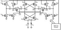
13_1291353050_thumb.jpg
[/url]

Thank you....
 

Your image doesn't open.
 

No , to minimize the power consumption they must be saturated or cutoff .

But during saturation, Vds of the transistor is greater than the Vds during linear.
With that, I believe switches (transistors) should be in Linear.....
 

You want to move as quickly as possible between linear (on)
and "off" because these are your two (almost) non-dissipative
states. If efficiency roll-up is primarily driven by switch
conduction losses, which is not to be assumed in a capacitive
charge pump.
 
hello dick_freebird...
I got confused with your statement.
Do you mean my desired state is LINEAR or CUTOFF and I need their transition to be pretty fast?
sorry if I can't easily grasp what you've tried to say.
 

Status
Not open for further replies.

Part and Inventory Search

Welcome to EDABoard.com

Sponsor

Back
Top