kazim
Member level 4
- Joined
- May 26, 2006
- Messages
- 77
- Helped
- 6
- Reputation
- 12
- Reaction score
- 3
- Trophy points
- 1,288
- Location
- Nowshera, Pakistan
- Activity points
- 1,838
dear friends
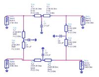
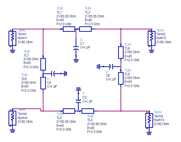
i am working on this paper published in IEEE [A Varactor Tuned Branch-Line Hybrid Coupler].
In the ads simulation i used only simple capacitors instead of varactor diode for tuning the hybrid.
i made up the hybrid coupler using ideal transmission lines working on 2 GHz. when i put in the capacitor and do a little sweep on the capacitors, the operating freq shifts but the coupling does not remain 3 db instead it goes to 6 db or more but in the paper the result from with in 1.7GHz to 2.1 GHz the coupling remains near 3dB.
i dont know whats the problem. can some one sought it out.
---------- Post added at 17:29 ---------- Previous post was at 17:27 ----------
is there a way to find out how much tuning is possible. i mean what would be the limit up to which the hybrid could be tuned