Continue to Site

Welcome to EDAboard.com

Welcome to our site! EDAboard.com is an international Electronics Discussion Forum focused on EDA software, circuits, schematics, books, theory, papers, asic, pld, 8051, DSP, Network, RF, Analog Design, PCB, Service Manuals... and a whole lot more! To participate you need to register. Registration is free. Click here to register now.

Filter design software

Status
Not open for further replies.

uoficowboy

Full Member level 3
Joined
Apr 4, 2009
Messages
169
Helped
6
Reputation
12
Reaction score
5
Trophy points
1,298
Location
Seattle, Wa, USA
Activity points
2,964
Hi - I see that there are quite a few filter design software packages out there.

Can anybody recommend one or compare some of them for me? I'm looking for software that will help me design low pass filters for data acquisition systems.

Thanks!
 

I use **broken link removed** by NuHertz. It is very versatile but it might be a little pricey...
 
Nuhertz is good - I have it myself. However, you requirements would probably be satisfied by Texas Instruments' Filter Pro which is free.

Keith
 
Nuhertz is good - I have it myself. However, you requirements would probably be satisfied by Texas Instruments' Filter Pro which is free.

Keith
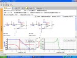
Hi Keith - thanks for the suggestion. I just played around with FilterPro and it is giving me some strange results. I asked for it to give me a -97db attenuation at 10KHz with 500Hz being my passband.

The filter it produced gives me about -180db at 10KHz. It seems like I don't need as high of an order of a filter as it is recommending. Am I missing something? Further, why are the the two stages different? What benefit does that yield? I would have assumed that you'd want your poles at the same place.

I've attached a screenshot showing my results.

Thanks!

-Michael
 

Attachments

  • FilterOddness.jpg
    FilterOddness.jpg
    120.8 KB · Views: 109

Your cursors are at 100kHz not 10kHz. If you look at 10kHz I think the attenuation is around 105dB which seems correct.

The two stages should be different. Filters use poles and zeros in different places to get the required characteristics, in particular, sharp cut-off. If you cascade several filters with identical characteristics you will end up with a very "soft" cut off. Sorry for the non-technical terms.

I have attached an example - two cascaded 2 pole Butterworth filters compared with a 4 pole.

Keith.
 

Attachments

  • Filters.pdf
    4.1 KB · Views: 121
Actually, this is probably a better example. It is a 4 pole Butterworth and shows the first stage response, the second stage and the overall response. The peak in the second stage is to help to "sharpen up" the cut off point while still giving a 4 pole slope after the cut-off frequency. The Filter Pro help may have some useful information about the different filter types and how they are made up.

Keith.
 

Attachments

  • filter 4 pole Butter.pdf
    8.3 KB · Views: 105
Actually, this is probably a better example. It is a 4 pole Butterworth and shows the first stage response, the second stage and the overall response. The peak in the second stage is to help to "sharpen up" the cut off point while still giving a 4 pole slope after the cut-off frequency. The Filter Pro help may have some useful information about the different filter types and how they are made up.

Keith.

Keith - that drawing definitely clears things up. I can clearly see now why you would want poles in different places.

If you don't mind, perhaps I could bother you with a couple follow up questions:

Perhaps I don't need as large of a stopband attenuation? I chose -97db as I am using a 16b ADC. 20*log(1/2^16) = -96.3db. I am trying to avoid any aliasing issues. So I chose 10KHz as my stop frequency as I plan on sampling at 20KHz. 500Hz is where I would like to have solid data, but faster would be better of course. So does -97db make sense for this? Now that I'm thinking more carefully about it - I suspect that that is overly cautious and I can get away with significantly less attenuation without any problems.

Will the phase shift of the circuit cause any issues? My control theory kung fu is a bit weak, but I thought going past 180 degrees phase shift caused major issues. The 4 pole filter suggested gives 360 degree phase shift. Is there any reason to avoid adding more poles? (besides additional component count)

How do I choose op-amps for this? My understanding is that certain filter topologies have vastly different requirements. Filterpro suggests a GBW of 27KHz for the first stage and 65.5KHz for the second stage. My reference on my ADC is 5V, so if I want less than 1b of error due to offset error in the OAs, I guess that suggests that I need a nominal input offset of 76uV or less (5/2^16 = 76E-6). Does that sound right?

Sorry for asking so many questions - this is just a very important topic to me that I want to make sure I fully understand.

Thanks so much!
 

Hi uoficowboy,

in case you need a pre filter for ADC purposes, don't forget that group delay requirements may be an important point leading to the necessity to choose a Thomson-Bessel response (instead of Butterworth).
 
Also the time domain behaviour of the filter may be interesting for measurement applications, a bessel (linear phase) filter is also good regarding step or impulse response.

The requirement for a steep pass- to stopband transition is usually set by the application, as in the case of an audio ADC, that wants to achieve 18 or 20 kHz bandwidth with 44 kHz sampling rate.
I think you and LvW are right - a bessel filter is probably the way to go. My application is data acquisition on a active load/battery analysis system. I don't know exactly what the noise will look like just yet, so it's not clear to me how aggressively I should be filtering, and what the dangers are of excessive filtering.
 

I think your calculations for the stopband attenuation are sensible if you don't know what frequencies the signal will contain. A four pole filter is not very complicated. You have already had useful advice on phase. A Bessel has constant group delay (but not constant phase) so you are going to get phase shifts. However, it will preserve pulse shape better than other filters.

With a 500Hz passband you won't have any problems finding a suitable opamp but be careful when you go to higher frequencies and larger filters - the opamp bandwidths required can get pretty high.

By the way, if your frequency of interest is 500Hz then you would want to put the 3dB point higher than 500Hz otherwise you main frequency of interest will have a 3dB error.

If you are measuring DC voltages and you want 16 bit accuracy then yes, you need a very low offset opamp.

Keith.
 
Hi uoficowboy,

perhaps the following article is helpful (filters for anti-aliasing and reconstruction)

**broken link removed**
 
hey..I used the filter software of microchip company and it helped me a lot. You can try that hope that will also help you a lot.

Wish you Good Luck.

MOD

Signature link removed
 
hey..I used the filter software of microchip company and it helped me a lot. You can try that hope that will also help you a lot.

Nevertheless, I prefer TI's Filter-pro because it is more versatile. In particular, Microchip's software supports Sallen-Key srtuctures with unity gain stages only which are not to be recommended.
 

What is not simulated or calculated is the coupling between the input and output from the physical layout. It is very difficult to get more than 60 dB rejection because of this coupling. The solution is to have two filters in tandem and have them physically separated.
 
What is not simulated or calculated is the coupling between the input and output from the physical layout. It is very difficult to get more than 60 dB rejection because of this coupling. The solution is to have two filters in tandem and have them physically separated.

Hi - I'm not sure what you mean by in tandem? can you elaborate on that? Do you mean that the op-amps should be in separate packages? Separated by some distance on the PCB?

Thanks!
 

Will the phase shift of the circuit cause any issues? My control theory kung fu is a bit weak, but I thought going past 180 degrees phase shift caused major issues. The 4 pole filter suggested gives 360 degree phase shift. Is there any reason to avoid adding more poles? (besides additional component count)
After a bunch of reading, I think I can answer this question now: I just have to make sure that the phase shift at the frequency my (closed loop) control loop is sampling at is less than -180 degrees. Otherwise I could have instability. Does this sound right?

Also, flatulent (or anybody else) - can you comment further on the inability to achieve greater than -60db gain? This has me very worried.
 

I think you are right that you want low phase shift at your frequency of interest so the phase shift in your stop band is not the critical one.

I haven't measured the stop band of my filters I have built but I think it would be a bad layout/design that could only achieve 60dB. 120dB should be achievable. I have achieved 80dB isolation between a transmitter and receiver of the same board on the same channel.

Keith

Thanks Keith - your insight and experience are very appreciated. Can you comment on what mistakes could be made in a layout that would cause worse rejection? My thoughts for the proper layout:

Keep digital traces/noisy traces/as many traces as possible away from filter
analog ground plane underneath entire filter section
minimize trace length
Try to avoid traces for filter crossing over each other or running in parallel with each other
Proper bypassing of OAs

Would having OAs in separate packages make any sense?

Thanks so much!

-Michael
 

Michael,

The usual stuff, as you say:

Physical separation where possible e.g. between input & output.
Ground planes.

If you have 4 layers that makes things easier because you can put a good integrity ground plane between the components and any possible tracking which may need to cross over the signal lines (e.g. power).

If you have two opamps with four poles it can be worthwhile using two single opamps although I must admit I have done some 8 pole filters with quad opamps (space forced that approach) and they worked fine.

Filter the power supply to each opamp separately - a small resistor in the power rails of each opamp and a BIG capacitor. At your frequencies it can be beneficial to use 100uF on each opamp. I have certainly found that on circuits that work down to low frequencies (and 500Hz is low).

I must say I don't often worry too much about isolation. Good layout practice, avoiding quad opamps and lots of decoupling seems to be enough. I have designed circuits with 100dB of gain and more and if the isolation wasn't any good I would have had an oscillator. And that was with a layout that had to zig-zag the signal path due to space constraints. A lot of RF receivers will have 120dB of gain or more and the same problem would occur if isolation was that difficult.


Keith.
 
Status
Not open for further replies.

Similar threads

Part and Inventory Search

Welcome to EDABoard.com

Sponsor

Back
Top