Continue to Site

Welcome to EDAboard.com

Welcome to our site! EDAboard.com is an international Electronics Discussion Forum focused on EDA software, circuits, schematics, books, theory, papers, asic, pld, 8051, DSP, Network, RF, Analog Design, PCB, Service Manuals... and a whole lot more! To participate you need to register. Registration is free. Click here to register now.

12v inverter battery charger

Status
Not open for further replies.

ipinimo

Junior Member level 1
Joined
Sep 7, 2010
Messages
17
Helped
3
Reputation
6
Reaction score
3
Trophy points
1,283
Location
Nigeria
Activity points
1,393
hi all,
am working on 300watt inverter which i intend to use 1 transformer for charging the battery and do the inverter work

the inverter is a sinewave type 12v to 230v
the transformer rating is 8v to 230v 300watt
i am using H-bridge for driving the transformer

i think it should be possible to charge the 12v battery with this 8v transformer either by using smps or somthing else
i want to ask, is it possible to use this transformer to charge the battery with the 8v output,
if yes how can i go about it
 

Hi,
You can use the transformer for charging but not SMPS. You have use the freewheel diodes in the MOSFET H-bridge as rectifiers and use that to charge the battery. For this, you need to make sure that the MOSFET gates are forced low and that the MOSFETs are turned off, otherwise there will be a short-circuit.
Hope this helps.
Tahmid.
 
  • Like
Reactions: ismu

    ismu

    Points: 2
    Helpful Answer Positive Rating
Thank you tahmid

is it possible to charge the 12v battery with the 8v coming out of the transformer even with the free wheel diode and the mosfet gate is off?
the output voltage of the transformer is 8v and my battery is 12v? if yes, how will i do it?
because am thinking the 8v is too small to charge it
pls any advice or idea is welcome thank you.
 
Last edited:
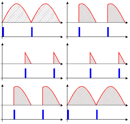
Yes, you can charge with the same transformer, but not 8v. What you need is a primary voltage control, either variable or fixed. This is usually done using a triac or 2 SCRs and another tapping in the transformer (I used 140v). The control of the triac/SCRs is done using phase angle control with either opamps (a complicated circuit) or if you can use microcontroller, then much simpler with a microcontroller. On the other hand, you CAN use a fixed voltage tapping, ie input 220v into another winding (eg 180 or such) adjusted such that the output is 12 or more voltage. However this would change the charging current with changing input voltage, so thyristor based is better.

Hope this helps.
Tahmid.
 

thank you for the reply
pls can u give me more detail on how to do it
especially about the firering angle and the Uc
thank you in advance
 
Hi,
Check this out:
220px-Regulated_rectifier.gif

Phase fired controllers - Wikipedia, the free encyclopedia
A sinusoidal AC waveform is divided up into 360 degrees, with the positive half and the negative half of the waveform combined into a kind of circle.

The firing angle simply refers to the point on the waveform, as measured in degrees (thus 'angle') which the thyristor is triggered into conduction.

or

Firing angle is the phase angle of the voltage at which the scr turns on. There are two ways of turning an scr on..one is by applying a gate current or by applying a voltage across the scr until it becomes greater than the breakover voltage....

Using the uC you control the time when the thyristor turns on thus controlling the firing angle.

Hope this helps.
Tahmid.
 
Status
Not open for further replies.

Similar threads

Part and Inventory Search

Welcome to EDABoard.com

Sponsor

Back
Top