Continue to Site

Welcome to EDAboard.com

Welcome to our site! EDAboard.com is an international Electronics Discussion Forum focused on EDA software, circuits, schematics, books, theory, papers, asic, pld, 8051, DSP, Network, RF, Analog Design, PCB, Service Manuals... and a whole lot more! To participate you need to register. Registration is free. Click here to register now.

What is a Quality Factor? Should its value be high or low?

Status
Not open for further replies.

testing test

Member level 3
Joined
Mar 3, 2010
Messages
65
Helped
5
Reputation
10
Reaction score
3
Trophy points
1,288
Activity points
1,656
Hello,

What is a Quality Factor? Should its value be high or low?

Thank you!
 

Hello,

In the electronics world, quality factor is mostly defined as the ratio between reactive power and real (loss) power.

In a series circuit of an inductor/capacitor and a resistor this becomes:

Q = 2*pi*f*L/R, Q = 1/(2*pi*f*C*R)

As the current in a series circuit is same for the resistor and the inductor/capacitor, this definition satisfies the basis idea.
For a parallel circuit it becomes:

Q = R/(2*pi*f*L), Q = 2*pi*f*C*R

Q factor is used to specify the loss behavior of inductors and capacitors. For example look at specifications for Coilcraft inductors. Note that the Q factor of a certain component varies versus frequency. Higher Q factor means less loss in the component.

Q-factor is also used for resonant circuits (crystals, mechanical resonators, LCR circuits, etc).

For resonance circuits (series LCR circuit)

Q = 2*pi*f0*L/R0

f0 = series resonant frequency where impedance is lowest and real.
R0 = impedance at series resonant frequency (real value).

Q = f0/deltaF

DeltaF = difference between two off-resonance frequencies where |Z|/R0 = sqrt(2). This is the same as where |Im{Z}| = R0 (so phase of Z = 45 degr).

There is a difference between the quality factor of a resonating circuit alone and the quality factor for a resonating circuit in a circuit (unloaded Q versus loaded Q).

Loaded Q-factor is of importance for example in oscillators. Doubling the Q factor of the resonator mostly reduces phase noise with 6 dB.
 
Re: What is a Quality Factor? Should its value be high or lo

What is the advantage of lower Q-factors? I have a spiral antenna operating at 12 GHz and the quality factor is approaching 0 at this frequency. How is it of any worth?
 

Re: What is a Quality Factor? Should its value be high or lo

In antennas if you want to increase antenna efficiency you should reduce the resistive losses this means that you should increase Q factor.I dont know which component do you use if you use coil you should decrease its resistive losses for efficiency.There is another way to increase antenna efficiency that is you can increase radiation resistance.There is no advantage to have low Q values.It means quality factor.
 

Hello,

In antennas you have generally two types of loss.

1. The loss due to the conversion from electrical energy into electromagnetic radiation (mostly the desired effect).
2. The loss due to heat loss in conductors and dielectrics. Sometimes this loss type is used deliberately to increase bandwidth of wide band systems.

As a receiving or transmitting antenna, mostly you don't want number 2 loss.

There is also a mismatch and polarization loss, but these ones I ignore for now.


The concept of Q-factor loses its usefulness in case of structures with BW/f0 > 1…2.

Regarding the 12 GHz antenna with (almost) zero Q, this is probably a spiral above a ground plane where the ground plane is filled with RF absorbing material.

This absorbing material reduces the radiation efficiency (rad. Eff. = radiated power / electrical input power), but increases the BW and/or increases the Return Loss as reflections from the ground plane back to the antenna are reduced.

In one sentence: the advantage of low Q-factors is large(r) bandwidth.
 
Actually spiral antenna are wide bandwidth and as q factor is inversely proportional to bandwidth, so I assume it must have low values of Q. My graph is almost like this IEEE paper curve:

93_1271961482.jpg


What I have done is placed a very high insulator substrate, then placed a insulator material acting as a oxide and placed the spiral above it. So, there is a big insulating material just below the spiral.

Q.So, should I assume the results are correct and help me achieve good bandwidth?

Q.Also, why would someone need to increases the Return Loss?
 

Hello,

From your last post, I don’t know what you are designing, is it an inductor (on purpose) or something that has to radiate (antenna)?

Some more info might be helpful
 

Re: What is a Quality Factor? Should its value be high or lo

That like asking "what is horsepower in a car engine, and should it be high or low"?

The answer depends on what you are trying to do with the car!
 

Re: What is a Quality Factor? Should its value be high or lo

WimRFP said:
Hello,

From your last post, I don’t know what you are designing, is it an inductor (on purpose) or something that has to radiate (antenna)?

Some more info might be helpful

Hi,

I have to design an antenna. But the manual i got to make it in a simulator is spiral inductor on silicon. Cant inductor act as an antenna?

Thank you.
 

Hello,

When you make the frequency high enough, almost every structure will radiate (except when fully enclosed by a good conductor).

Metallic structures will radiate easier when their size is no longer small compared to the wavelength belonging to the frequency of the source.

In most cases you want to have a predefined radiation pattern, predefined input impedance, radiation efficiency and useful bandwidth. In such cases antenna design becomes important.

To learn how to use the simulator, it is best to start with some simple standard antenna designs (halve wave dipole, rectangular patch antenna, etc). Check whether your simulation results match published data.

To learn how to shape a metallic structure so that it behaves as requested, requires you to study antenna design. In many cases a standard design can be modified to fit your requirements, but you need to know some basics about relation between current in a structure and generated far field. Many antenna structures behave like transmission line sections, so you need to know transmission line theory also.

In narrow band antennas the current distribution is mostly dictated by standing wave behavior (half wave patch antennas, half or full wave dipoles, slot antennas, small loops, etc). In wide band antennas, traveling wave behavior is dominant (various horn antennas, spiral antennas, flared/curved transmission lines, etc).

The difficult to understand antennas are the ones where multiple resonating structures are used to get wide bandwidth.

When you need a more specific answer, you should provide the community some specific information about what you want (frequency, radiation pattern, production method of antenna, polarization, bandwidth, study or actual design, etc).
 
Re: What is a Quality Factor? Should its value be high or lo

The above Q diagram is obviously related to an inductor, that can be described mainly by a lumped element equivalent circuit.
This is another word for being sufficient small related to the signal wavelength and not acting as an antenna.
 
Re: What is a Quality Factor? Should its value be high or lo

FvM said:
The above Q diagram is obviously related to an inductor, that can be described mainly by a lumped element equivalent circuit.
This is another word for being sufficient small related to the signal wavelength and not acting as an antenna.
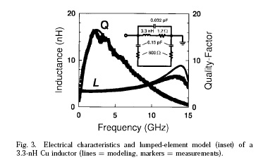
But this is the Q factor diagram for spiral antenna then why are you saying it's not an antenna?
 

Re: What is a Quality Factor? Should its value be high or lo

If it's an antenna, it must have dimensions, that are not small related to the wavelength. Then it's a distributed circuit and can't
be represented by a lumped element equivalent circuit for a wider frequency band. A lumped element equivalent circuit for an
antenna could be valid only for a bandwidth of a few percent around the operation frequency.

But this is just a general remark. Unfortunately, you didn't tell yet any dimension information. So we don't know, if your spiral
inductor can work as an antenna. An electrical small antenna (< λ/2) has a high Q respectively a small bandwidth, if it's effective.
 
Re: What is a Quality Factor? Should its value be high or lo

I have attached the manual which has all the information and dimensions. Please look into the issue.
 

The example spiral inductor has dimensions below 1% of the free space wavelength at 12 GHz. It can't effectively work as an antenna.

P.S.: Basically, a spiral inductor can be analyzed as small magnetic antenna. The radiation resistance will be however very
low and most likely not suitable for any wireless transmission purposes.

An ideal antenna with a low radiation resistance would also have a high antenna Q. The spiral inductor has low Q due to it's resistive losses.
 

Hello,

As what FvM said, this structure is too small to be a good radiator. At 12 GHz the free space wavelength is 25mm. The size of your structure is 60um (0.25% of wavelength). Regarding the "size": the largest size is of importance, not the coiled wire length. When there are no dielectric or ohmic losses, this structure would have a Q-factor > 1000, hence a radiator with very small useful bandwidth. As the data shows Q-factor < 20, the radiation efficiency of this coil as a radiator wil be less then 1%.

As you are designing an inductor, it is required that loss due to radiation is low, hence the small size w.r.t. wavelength.
 

How much percent of wavelength should the dimensions of an antenna be to make it a good radiator?
 

high Q for low phase noise and low Q for wideband matching
 

Status
Not open for further replies.

Part and Inventory Search

Welcome to EDABoard.com

Sponsor

Back
Top