Continue to Site

Welcome to EDAboard.com

Welcome to our site! EDAboard.com is an international Electronics Discussion Forum focused on EDA software, circuits, schematics, books, theory, papers, asic, pld, 8051, DSP, Network, RF, Analog Design, PCB, Service Manuals... and a whole lot more! To participate you need to register. Registration is free. Click here to register now.

Comparator overshoot and oscillations - how to fix?

Status
Not open for further replies.

Zangetsu57

Member level 4
Joined
Aug 23, 2007
Messages
70
Helped
1
Reputation
2
Reaction score
0
Trophy points
1,286
Activity points
1,944
Hello everyone,

What I'm doing is developing a circuit that can take two square wave inputs (LVTTL) that are offset by a very short period of time (offset on the order of several hundred picoseconds to several nanoseconds), then output which signal reaches a specified DC threshold voltage first. The thought is to use the LT1720 dual comparator to compare the two signals to a DC voltage (150mV in this case), then feed the output to an OR gate.

The problem I'm having is the OR gate output overshoots and oscillates quite a bit before settling. I removed the OR gate from the circuit, and noticed that the output of the LT1720 comparators also overshoots quite a bit, oscillates, then finally settles. It does this when the state changes from low to high and high to low. The current rise time is about 2.5 ns. I'm thinking that if I simply reduce the rise time by increasing the RC time constant for the output, this will fix itself. I'm not entirely certain how to accomplish this, however, since adding a more resistive load doesn' t seem to affect the rise time.

Here is what I've done to try and remedy the issue:
1. Ensure good supply bypassing. Not the problem. I'm using a 10nF ceramic, 2.2 uF tantalum, and 10uF tantalum capacitor within 1 cm of the IC.
2. Check the input signal for overshoot. It is a very clean signal with about 20ns rise time, so that isn't the problem.
3. Check for good grounding. I don' t think this is the issue either, and I've tested jumper wires to see if this affects the output.

The only thing I can think of is the outputs are close together, and perhaps there is some capacitive coupling going on.

I'd be indebted for any assistance. I've tried to fix the problem, but am out of ideas, and graduation is near and I need to get this thing working.

Thank you!

EDIT: I've uploaded pictures of the overshoot off the scope. Note that I'm using an old 100 MHz tektronics scope, but I've double checked that the problem isn't limited by the bandwidth of the scope by using a 50 ohm 16 GHz digitizing phosphor tektronics scope (which just isn't ideal since it is for RF devices and has low input impedance).

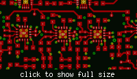
EDIT 2: Uploaded Layout of bottom. Red x's indicate vias.
 

Hi,
GND-ing is a issue:-(...
Check C1&C2, where is GND coupled to the speedy IC? You have a loop of cm`s!

Where is GND-TOP connected to the GND BOTT: only at BNC (like) Connector, you must have some Vias minimum at the Comparator/OR gate between GND Plane & Bypass elements & IC GND-Pins...
These Vias are unseeable for me!
K.
Otherwise; I would take other comparators(higher speed) if the sensed time difference is at nsec!
Their are with outputs (open drain), that you can use as wired OR automatically:), one IC less on the board....

Added after 6 minutes:

Than, C1 is direct at IC to place, the Tantal can be some cm away from it...
Pls, rotate both C`s to the midle of IC & put a Via under IC to the other layer.
Is your otput cable/scope input terminated with 50 Ohm?
K.
 

    Zangetsu57

    Points: 2
    Helpful Answer Positive Rating
Hello karesz,

First off, thank you for your speedy response. I uploaded a new image of the bottom where I installed vias. They have been there, but I never bothered to update the schematic. Perhaps I still need to add more? It is worth a try.

Note that I currently removed the OR gate and put 1k load on the outputs of the comparator. I'm going to cleanup that signal first, then put the OR gate back. I'm probing with a 1Mohm oscilloscope (see above in EDIT1 of post for more info).

I apologize, but I'm having some difficulty understanding your statement "therwise; I would take other comparators(higher speed) if the sensed time difference is at nsec!
Their are with outputs (open drain), that you can use as wired OR automatically:), one IC less on the board.... "

Are you saying I can use the current LT1720 as an OR somehow? Just to recap, I'm doing a time sensitive measurement where two pulses are arriving at a short time interval apart (as low as 100ps), and I want whatever one reaches 0.15V threshold to be output first. A high speed OR gate accomplishes this, but maybe there are better alternatives. The application is to start a timer on a time to digital converter.

Unfortunately I don't have the time to do a redesign, so hopefully I can make this work somehow.

Thanks for any additional help!
 

I have designed laser rangefinders and am familiar with your sort of circuit. It is very difficult to probe them - you need to use very short tip probes with attached grounds and even then it is difficult to believe the results above 200Mhz- 400MHz with 1M probes despite what the probe manufacturers say. So, be sure you are probing correctly and are sure of what you are seeing. Ideally you would have a 50ohm system and could then probe it with a 50 ohm probe by removing the PCB load - then you can trust the results a bit more.

I have a couple of different "high impedance, low capacitance" RF probes which I use and are specified at 1.5GHz and 3GHz. One is a passive 20:1, the other an active FET probe.

I don't think the LT1720 is really that fast: 4.5ns delay, 2.5ns rise time. I have used the ADCMP573 for such applications: 165ps delay, 35ps rise time. You will have some limitations to how well you can get it to work simply by the slow speed and slew rates.

Anyway, it is worthwhile looking at the power supply with a fast scope (ideally 50 ohms with a capacitive coupling). You might see the "overshoot" on there as well. 10nF is far to high for decoupling at these sorts of frequencies - a typical SRF will be around 40MHz! On the ADCMP573 I used 47pF, 1nF, 47nF & 1uF. You certainly need something no larger than 100pF. In some cases I have found using two small values useful.

How are you getting the signals on to the board? It looks like it is by some pins. If so, you really need coax and a 50ohm terminated system and the grounds for terminating the coax need to be very close to the IC input.

As already mentioned by karesz, as you have two ground planes you need a lot more vias between them. With a double sided board I would probably have only used the top as a ground plane but as you have both sides I would say it should be littered with vias at say 10mm intervals in both directions.

Your decoupling capacitors are too far away from the IC and in particular you should always put the lowest value closest. That one is your main defence against high frequencies and so inductance is critical.

What produces the signal for the comparator input?

It is tricky to modify an existing PCB, but maybe you can add some better decouplers close to the chip, drill a few vias & add wire links and work on getting a good signal on to the board. There is no guarantee which measure will fix it - you have to just try things and look for an improvement each time.

Keith.
 

    Zangetsu57

    Points: 2
    Helpful Answer Positive Rating
Hi,
I missed my answer from ca. 30 mimutes ago...
I asked: How long is your GND lead pls? I assumed that you has a TDC application:)...
K.

Added after 4 minutes:

As Keith tells too: Probing can be a problem, first line the GND loops/leads! and of course GND-system of PCB.
You can build a selfmade 500Ohm or max2-5KOhm probe, with todays SMDs it isnt a problem.
Otherwise I makes GHz (pulse)electronics over 20 years and dont have so a probe:), but I hav hade every time Tek`s Active FET-Probes, and a good old analoge scope of 400MHz, some time borrowed the 1GHz brother...
Teen years ago I buyed (for the firm) Europas first HP54000 (if Im right; with 2GHz repetitive bandwith)...
It was of course an total other category!

Added after 8 minutes:

You should have at the comparators threshold good uFs-as tantal too(or the 2.2uF ceramics)_the serial trimmer isnt good idea!I would make the adjustment befor apply a buffer + good bypass capacitors...
I meaned some similar, but didnt find yet: MAX9961/MAX9962 Dual, Low-Power, 500Mbps ATE Drivers/Comparators ..
 

    Zangetsu57

    Points: 2
    Helpful Answer Positive Rating
The Tektronix P6158 20:1 passive probe is the lowest cost "useful" high speed probe. It is 1k to 50 ohms so still loads your circuit a bit, but better than 50 ohms. Across a 50 ohm circuit the load mismatch is not too bad.

Keith.
 

    Zangetsu57

    Points: 2
    Helpful Answer Positive Rating
@Zangetsu57,
You must take i.e. MAX9600, or some similar from ADI (in, for me more sympatic, LCC20 package), both families are potent to have min. 100psec resolution...
Becouse they are ECL comps; you can the short Qs and so build a wired-or:)_automaticly!
Other possibility is Motorolas ECLinPs family_a line receiver used as comparator!:) Their are up to Gbps usable too...
Of course these ICs needs more power & better bypassing!
I have hade a project ca. 18 years ago, with ADIs sayd comparators_i ordered it from ADI in LCC20 package, it wasnt a catalog product, only after so 5 years, but for us are ca. 1200 boards used over 15 years:)...
K.
 

    Zangetsu57

    Points: 2
    Helpful Answer Positive Rating
karesz said:
@Zangetsu57,
(in, for me more sympatic, LCC20 package)

Yes, ADCMP573 is only in LFCSP - I hate those packages! And you need to be careful - some packages look identical but have a slightly different footprint.

Keith.
 

    Zangetsu57

    Points: 2
    Helpful Answer Positive Rating
For so critical & high-speed circuits is very usfull the Cs on the backside to have!
As Keith told too: every times i.e. 1nf (ev. some smaller) at IC, than 50-100nF and to end the uFs, specifically C-system values: depends on IC-families speed!...
On existing board you should put a 10 nF to IC2/pin 4 direct, then pull C1/C7 and rotate to midle of IC1, but 10nF to IC direct &apply a via at GND(i.e. nearest to IC1/pin4, but by IC2/pin bypassingsGND too!
Other one Via is needed between IC2/pin1 & IC1/pin8 too!!
These is "HF practice" for godd HF_ GND-System: "so near as possible & often as possible"...
K.

Added after 4 minutes:

Is it possible, that your R4/C8 arnt on GND_I dont see a Via!?
 

    Zangetsu57

    Points: 2
    Helpful Answer Positive Rating
karesz said:
Is it possible, that your R4/C8 arnt on GND_I dont see a Via!?

Well spotted! If you look at the layout you can see the unconnected net ratsnest as well.

Keith.
 

    Zangetsu57

    Points: 2
    Helpful Answer Positive Rating
Thanks for the replies everyone! Let me respond in order:

@keith1200rs: Thanks for the information regarding the probes. I think they may very well be the problem. I jumped the LT1720 output under test to the BNC connector then to a BNC -> SMA adapter and took a look on our 16 GHz RF digitizing oscilloscope. The signal was much cleaner! The only thing is the amplitude was not very high, but I think that's because it is designed to drive load 250 ohms or greater, not 50 ohm loads. Is there a better way to test this?

I'll consider the ADCMP573 in the future in redesigns too if I continue this work after graduation. I didn't know faster parts existed, and the best I could find was the LT1721.

The signal for the comparator input is the output of an AGC circuit - the AD8367. Ideally the signal would have fed directly into the LT1721 from microstrip traces. The "Tstart" board is a quick fabricated prototype that I added later on in the design that works alongside two pre-fabricated boards. Suffice to say, I didn't want to fabricate another board just to test a concept. So, the feeds are short jumper wires about 5" in length. I know this isn't ideal.

I'll also try adding a XX pF capacitor for additional decoupling. I do notice periodic noise within the ground plane - spikes that correspond to the high speed transitions of the comparators. My best guess is these are high frequency components that aren't filtered out.

Added after 6 minutes:

@karesz

The ground leads are about 6" if I were to guess. Probably too long. The probe capacitance is also 11.8pF if I remember correctly, and 1MOhm.

As for the lack of the via, there is actually one there. I just forgot to mark it :). Nevertheless, I'll be adding more throughout the board this afternoon. I had no idea they were so critical. I'm more of an electromagnetics/microwave engineering student so I'm still learning about high speed electronics and proper layout :).

I appreciate all of the advice everyone has given!
 

Zangetsu57 said:
... the amplitude was not very high, but I think that's because it is designed to drive load 250 ohms or greater, not 50 ohm loads. Is there a better way to test this?
Yes, you can apply minimum a serial 47/50 Ohm termination_so you have a properly driven 50 Ohm system=2:1 attenuator and not a possible overload through 50 Ohm scope input...What about "AC(end) termination" pls?

Zangetsu57 said:
.
I'll consider the ADCMP573 in the future in redesigns too if I continue this work after graduation. I didn't know faster parts existed, and the best I could find was the LT1721.
Be care pls with it!
Its a very speedy component; you will be to handle frequencies up to ~10 GHz! You must not over qualified components select if is possible!
At these much GHz frequencies you will become lot of (unconventional) problems with realizations: begins with PCB & Capacitor materials, then probings & biasing techniques...
I would take only so speedy components as the circuit it need, maybe are the Maxim comparators enough for that_eventually the older ADI types...
For example the PCB routing:
If you has rise time at 100ps; you need an impedance undefined copper line length
of max ca.12-15psec:-((... Do you know pls how long (distance) its on PCB?

Apropos probing:FORGET BNCs_their arnt good HF conns & with a plus SMA adapter it will not better!! Why can you not direct a SMA Conn apply or other similar HF connector-system_eventuel "N or 7mm..."?
You must by so high frequencies over all test points forseen_its not unconventional (theoreticaly), but you must not think over a scope probe tip on it, but their are as SMA conns to realize and you need stabile 50 Ohm cables as test tips! (of course with the serial (source) 50 Ohms to their)

Zangetsu57 said:
....I'll also try adding a XX pF capacitor for additional decoupling. I do notice periodic noise within the ground plane - spikes that correspond to the high speed transitions of the comparators. My best guess is these are high frequency components that aren't filtered out.
Exactly, because your bypass Cs are really not perfect_pls refer to my earlier comments, then a tip GND-lead of 6" is nothing for pulsetechnique_sorry, you are in frequency domain of some GHz here_ you need GND-lead of cm, not 10-12cm....
These is the most reason for your overshoots_its an inductive answer!
Dont forget pls,
for bypass Cs at GHz frequencies (100pF/1nF/10nF) you must have HF proof materials_minimum COG, better porcelans, i.e. from ATC...
The bigger values as 10, 100nF are i.e. as X7R but not as Y5U/V... to select.

Zangetsu57 said:
@karesz
The ground leads are about 6" if I were to guess. Probably too long. The probe capacitance is also 11.8pF if I remember correctly, and 1MOhm.
You must build your quasi HF- probe, or use a FET-probe!
12 pF will be to much in the most HF circuits, active probes have only ca1-1.5pF:)
So a tool is easy to build!
Zangetsu57 said:
I'm more of an electromagnetics/microwave engineering student so I'm still learning about high speed electronics and proper layout :).
No problem, these is a good school stuff for you:)...
Karesz
 
... as karesz said!

Also, for looking at the output you could use a simple T attenuator - say 250 ohms in, 50 ohms out to feed the scope 50 ohm input through some coax to avoid loading your circuit too much.

"short jumper wires about 5" in length" is an oxymoron! 5" jumpers are looonnnngg at these frequencies. You could try some coax and use a T attenuator there, although you will lose some signal. There is an example in the AD8637 data sheet on page 19. You could use the same values for a 'scope connection from the LT1721. Remember to terminate the coax at the LT1721 input.

You cannot really probe with normal 'scope probes at 10pF to 15pF. A T attenuator matched to some coax feeding a 50 ohm scope input would work though.

By the way, I use Eagle if you ever want someone to look over a board before you make it.

Keith.
 

    Zangetsu57

    Points: 2
    Helpful Answer Positive Rating
You can find some basic techniques, descriptions over HF measurements...
K.
 

    Zangetsu57

    Points: 2
    Helpful Answer Positive Rating
keith1200rs said:
... as karesz said!

Also, for looking at the output you could use a simple T attenuator - say 250 ohms in, 50 ohms out to feed the scope 50 ohm input through some coax to avoid loading your circuit too much.

"short jumper wires about 5" in length" is an oxymoron! 5" jumpers are looonnnngg at these frequencies. You could try some coax and use a T attenuator there, although you will lose some signal. There is an example in the AD8637 data sheet on page 19. You could use the same values for a 'scope connection from the LT1721. Remember to terminate the coax at the LT1721 input.

You cannot really probe with normal 'scope probes at 10pF to 15pF. A T attenuator matched to some coax feeding a 50 ohm scope input would work though.

By the way, I use Eagle if you ever want someone to look over a board before you make it.

Keith.

Thanks for the advice, but I don't see how a 5" jumper is going to make a huge difference. The input signal has a rise time of about 10ns, and the comparator rise time is about 3ns. The maximum frequency component of the signal is about 0.35/Tr = 116 MHz (assuming a Gaussian response). In FR4, this means a 5" cable (assume same dielectric constant as FR4 to be safe, even though it is probably less), has a wavelength of 0.1*lambda. This isn't *that* bad, right? I recall reading that a tenth of a wavelength is about when you start to care about transmission line effects, so this is right on the edge. But hey, I don't have the experience you guys do :).

Thanks for the offer, Keith. I wouldn't mind learning a few things from someone who I gather has been working with high speed electronics for years :).

Added after 27 minutes:

Here is something that I've been thinking about for a while, and haven't been able to find an answer: at what frequency should I start to care about designing transmission lines with a specific characteristic impedance for parts like this? And then, what should the impedance be?

In later boards, should I design the widths of all traces to achieve 50 ohms? Is this critical for the LT1720 and similar parts? The confusion I have is the device can't drive less than 250 ohms DC resistance. How would you properly design such a circuit?

Oh, one last thing. I'm using LT1720 and LT1721 as threshold detectors that feed into the ACAM ATMD-GPX system, for anyone who is familiar. It is a Time to Digital Converter (TDC) with 81ps resolution in I-mode (8 input stop channels, 1 start channel) which is what I'm using.

Thanks again for everyone's help!
 

Zangetsu57 said:
...I don't see how a 5" jumper is going to make a huge difference.
These can be_sorry, but the life present it others!_I think you can agree with me?
Zangetsu57 said:
...The input signal has a rise time of about 10ns, and the comparators rise time is about 3ns. The maximum frequency component of the signal is about 0.35/Tr = 116 MHz (assuming a Gaussian response).
Pls dont mix two things!
Your source has 10ns (but I think; not after 12 cm wire..) & outputs rise time= 3nsec are independent, & dont means that your comp internal works only with that bandwidth...
These is reason of need for very good and wide bandwidth bypassing!

OTHERWISE: 0.35/3ns=IS NOT 116MHz maximum bandwidth_its ABSOLUTE ERROR!!

These 116MHz = 3dB bandwidth_you learned it surly, then for a more or less square pulse form YOU NEED the 5th-10th harmonics(minimum)? Also you has a system to use/built with a bandwidth of PRACTICALLY 1GHz!

Maybe; you will nothing find over that (so wroten) in school books, but HF-electronics works so:)....

I asked you some answers befor if "you knows how long copper line has a delay of 12-15psec?" I become nothing as answer, but it has a Nr of cm as value:)!
Zangetsu57 said:
..In FR4, this means a 5" cable (assume same dielectric constant as FR4 to be safe, even though it is probably less), has a wavelength of 0.1*lambda. This isn't *that* bad, right? I recall reading that a tenth of a wavelength is about when you start to care about transmission line effects, so this is right on the edge. But hey, I don't have the experience you guys do :).
No, no materials has the same dielectric constant_because their are not the same materials:)... Their has only similar, then minimum vs. frequency is their characteristics others!
You can find out over FR4 Epsilon-r too: it has values of ca 4 up to ca. 4.8, depending of specifically vendor and type/version of that, then its not "The Material", its only a category!!
You must so think over that:
5"=ca 25cm as reflections distance; its ca. 1.0-1.5 nsec, at these time has it the ringing/glitches on your signal! Otherwise; if you say: it has 1/10 of the rise time to terminate=>>> you has only ca 300ps delay-(1)way as possible unterminated in accordance of these theory!
These is reason why is asked you some earlyer; how much cm are on copper the ca.15psec?!
Also, 300ps=ca. 7 cm distance on FR4.
If you are thinking over usage of 8Gbit components, their has a 100psec rise time system=you has only signal ways of less as 1cm as unterminated, you must know to handle very precise!!
At these time you has lot of problems with ca 40 times slower system! Its not a problem, if you will learn from it!:)
Zangetsu57 said:
...at what frequency should I start to care about designing transmission lines with a specific characteristic impedance for parts like this? And then, what should the impedance be?
You has practically the answer yet-over that.
Its NOT explicit AN EXACT FREQUENCY as limit to set! But ITS THE RISE TIME AS A MEASURE FOR THAT! The system bandwidth is to calculate from needed rise times, as you told it too... After that is knowed, you has the 1/8...1/10 as possible undetermined signal ways length, over that cm values are all copper(signal) lines as impedance defined to realize_minimum a serial resistor needed at your source).
The value of impedance= is your subject (& from driving capability)!
It can be from ca. 20 Ohm up to 1...200 Ohms, but practical are 50 & 100 Ohms.
If you has buried impedance lines & you wish 100/200 Ohms: its possible (depend of your PCB construct) that your trace widths will need be only i.e. 30um!(=UNREALISTIC)_of course, in that situation you must have i.e. 50 Ohm, or so, or other PCB system!

I believe, the LT1720 is not the best component for these job!!
I can believe for you, that some products has it build in, but it exists better components/way to go on (maybe yet is datum 10 years later:)): why is it not to select/go on?

Otherwise is a TAC not better for your measurements system?
A started loading and stopped charging is in my opinion better to realize...
K.
 

    Zangetsu57

    Points: 2
    Helpful Answer Positive Rating
I agree with what karesz says (the English is a bit tricky at times, but I understand the sentiment).

With regard to the effect of 5" of free interconnect, you can view it as an unterminated transmission line, as karesz says, or as an inductance with some capacitance and load impedance which will 'ring' even with 10ns edges. You will also probably find you can vary the pulse position by moving your hand near the board.

When you need to use transmission lines depends on distance as well as frequency. I have used transmission lines on video boards (a mere 4MHz). It does no harm and I don't want to find out I should have done by getting a problem when I test the PCB. On some of my high speed boards there aren't any transmission lines because I place parts so close there is no need. Also, the pads of high speed parts are too narrow for 50 lines on a double sided FR4 so you need to fan out from the pad which is not always easy. Normally my boards are 4 or 6 layer anyway.

If the chips are not 50 ohm you don't have to use 50 ohm transmission lines. 250 ohms would be one possibility. Bear in mind you lose half you signal with a terminated transmission line.

Keith
 
Just wanted to thank karesz and Keith for their comments in this thread. I am
going to use the ADCMP573 to generate a square wave from a sine clock
source, and this thread provided me with a lot of info. Read: A lot of things
to watch out for. So thanks. :)

Oh, question...

The ADCMP573 is a reduced swing PECL (RSPECL) device. My understanding is
that I can connect this output to an LVPECL (either 3.3 or 2.5 Volt) input.
Is this correct? To be precise, the ADCMP573 output will be connected to an
IOB on a spartan-6.

And now that I think about it, another question. This is related to
something Keith said regarding transmission lines.

keith1200rs said:
When you need to use transmission lines depends on distance as well as
frequency. I have used transmission lines on video boards (a mere 4MHz). It
does no harm and I don't want to find out I should have done by getting a
problem when I test the PCB. On some of my high speed boards there aren't
any transmission lines because I place parts so close there is no need.
Also, the pads of high speed parts are too narrow for 50 lines on a double
sided FR4 so you need to fan out from the pad which is not always easy.
Normally my boards are 4 or 6 layer anyway.

I do a lot of my prototyping dead bug style. I take a double sided FR4
(because these are cheap and plentiful), tin one side because I only use the
one side, and put the IC's on it upside down. Use smd R's + C's etc, and do
short point to point connections using thin wire. I conform the wires to run
as close to the ground plane as possible. So far this method has suited me
well. I can get things to 500 MHz easily, and haven't needed any higher
frequencues than that ... up until now.

Now I have a sine input that is up in the GHz's, and would like to prepare
for the surprises I will no doubt be getting. I would like to be able to
take in a ~ 1 - 4 GHz sine, possibly square it depending on the prescaler I
will use, send that sine or square wave through the prescaler, and send the resulting
200-800 MHz signal to an FPGA. The FPGA in this case being the aforementioned
spartan-6.

My main concern is prototyping the part that handles the 1 - 4 GHz sine. Given
that my prototyping style is dead bug on FR4, how do I feed the 4 GHz signal into the
prescaler? Can I get away with just a thin wire straight through the air from
the type N connector straight to the prescaler input? If yes, what would be
a reasonable length? 1 cm? 2 cm? 3 cm? Also, would I be better of using a
straight straight point to point connection? Or would I be better of by
conforming the wire to be as close to the ground plane as possible.
Conforming the wire to be right on the ground plane would IMO have as
advantage better shielding from EMI and as drawback needed a slightly longer
wire.

And now for the wires between ICs....
Keith said that for short runs it was in some cases useful to NOT use a
transmision line. This I can imagine, but I lack practical numbers. For
the dead bug style as described, and a signal of 4 GHz, what would you
consider a practical maximum wire length between parts?

Thanks!
 

If you read the datasheet for the ADCMP573 carefully you should be ok. Looking at my circuit using that device I have used 3V to pin 8 (VCCO = 5V in my case). Then I terminated the two outputs to the 3V with 50 ohms resistors. If you use a lower VCCO I think you need to use a lower pin 8 voltage (2V below VCCO),

I would think that you will be using transmission lines everywhere at 4GHz unless components literally butt up to one another. There is probably a rule of thumb someone can give to say when you should use them (> a tenth wavelength maybe so 5mm?). For my board with ADCMP573 I hardly needed to use transmission lines - I managed to get most things right next to the next component. Mind you, I used 6 layers and buried some transmission lines in the inner two layers.


I don't think you want any bits of bare wire around. Use coax.

You will want either thin board, some fancy Rogers material or 4 layers or more to make sure the transmission lines are sensible widths.

Keith.
 
According to the ADCMP573 datasheet, for pin 8 ...

Termination Return Pin for the LE/LE Input Pins.

For the ADCMP573 (RSPECL output stage), this pin should normally be connected to the VCCO – 2 V
termination potential.


So just like you say, I will use 2 volt below VCCO.

And thank you for the layout snapshot, always good to have some inspiration. In notice you did not connect pin 6 (/LE, the latch enable, inverting side), and as far as I can tell a pull up resistor from LE (pin 7) to the VCCO. Since I intend to use it in compare mode (LE=high) I take it from your usage of /LE + LE that I only need to connect to LE. For a static LE=high that is...

I also notice you used the HYST with an external resistor. Did you find any gotchas, or just working as advertised?

regards
 

Status
Not open for further replies.

Similar threads

Part and Inventory Search

Welcome to EDABoard.com

Sponsor

Back
Top