umery2k75
Advanced Member level 1
diathermy machine
I have got an old short wave diathermy machine to be updated from analog control to digital one. It was made on 1996 by some students of undergraduate. I don't have any final year report as it was misplaced long ago. I am tracing schematic of that circuit, it's taking me time because it's too untidy and worst kind of wiring is done, which I never had seen else where!
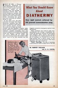
Anywayz dad give it a look and told me it's simply a RF oscillator, don't know whether he added it's Hartley oscillator or not. It contained two Vacuum tubes Pentode PL36 and a big variable capacitor and two BIG ferrite transformer, I think they make 500V from 220V will confirm it later on after schematic is done, he told me vacuum tubes are arranged in a push-pull manner. My task over here is to remove the mechanical timer and add the stepper motor to the variable capacitor to change the value, I also don't know what the big capacitor is doing over there, the timer that is found in traditional Oven, once turn on, they give sound "Tick,tick,tick" until the time gets over and extra modification is to be done on the user side that include current sensing and other stuff. I was told the circuit is OK and works fine by students, I don't have PADs available for treating the patient, neither they have. They asked from local market, the shop keeper asked about that machine and they simply don't know anything about it. I'll pay him a visit so I can understand what he's trying to say.I don't find technical stuff on the internet regarding this machine. I don't know have any contact to the students who made this machine in 1996.I'll upload the picture of the machine and also the schematic that I am tracing. I want to know why vacuum tubes were used in that machine, as I have seen in the picture below that diathermy machines are only about 200-400W only. I had downloaded a book from the internet which contains a chapter on Radiotherapy, there a circuit was given. I think that solid state semiconductor like a MOSFET, IGBT, BJT can work in a push-pull configuration and there would not be any need for vacuum tubes used over here. I had also seen the line filter in it, dad told me it's for isolating the frequency going back into the power line, ordinary bulb might not have any problem, but If I'm using computer or anything of electronics, it could have a problem as the line would be noisy.
The book that I had downloaded contains a chapter on Radio Therapy in which Short wave Diathermy machine was explained, the book name is "Radio HandBook, 1940". I think maybe students copied that machine from another machine of old time and that design might contained a vacuum tube, so that's why this design also contain vacuum tube. I think that vacuum tube could be replaced by some semiconductor. The schematic diagram that I had found on this book is
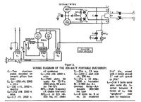
www.pmillett.com/Books/radio_hb_7.pdf
I have got an old short wave diathermy machine to be updated from analog control to digital one. It was made on 1996 by some students of undergraduate. I don't have any final year report as it was misplaced long ago. I am tracing schematic of that circuit, it's taking me time because it's too untidy and worst kind of wiring is done, which I never had seen else where!
Anywayz dad give it a look and told me it's simply a RF oscillator, don't know whether he added it's Hartley oscillator or not. It contained two Vacuum tubes Pentode PL36 and a big variable capacitor and two BIG ferrite transformer, I think they make 500V from 220V will confirm it later on after schematic is done, he told me vacuum tubes are arranged in a push-pull manner. My task over here is to remove the mechanical timer and add the stepper motor to the variable capacitor to change the value, I also don't know what the big capacitor is doing over there, the timer that is found in traditional Oven, once turn on, they give sound "Tick,tick,tick" until the time gets over and extra modification is to be done on the user side that include current sensing and other stuff. I was told the circuit is OK and works fine by students, I don't have PADs available for treating the patient, neither they have. They asked from local market, the shop keeper asked about that machine and they simply don't know anything about it. I'll pay him a visit so I can understand what he's trying to say.I don't find technical stuff on the internet regarding this machine. I don't know have any contact to the students who made this machine in 1996.I'll upload the picture of the machine and also the schematic that I am tracing. I want to know why vacuum tubes were used in that machine, as I have seen in the picture below that diathermy machines are only about 200-400W only. I had downloaded a book from the internet which contains a chapter on Radiotherapy, there a circuit was given. I think that solid state semiconductor like a MOSFET, IGBT, BJT can work in a push-pull configuration and there would not be any need for vacuum tubes used over here. I had also seen the line filter in it, dad told me it's for isolating the frequency going back into the power line, ordinary bulb might not have any problem, but If I'm using computer or anything of electronics, it could have a problem as the line would be noisy.
The book that I had downloaded contains a chapter on Radio Therapy in which Short wave Diathermy machine was explained, the book name is "Radio HandBook, 1940". I think maybe students copied that machine from another machine of old time and that design might contained a vacuum tube, so that's why this design also contain vacuum tube. I think that vacuum tube could be replaced by some semiconductor. The schematic diagram that I had found on this book is
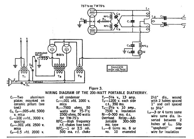
www.pmillett.com/Books/radio_hb_7.pdf