Continue to Site

Welcome to EDAboard.com

Welcome to our site! EDAboard.com is an international Electronics Discussion Forum focused on EDA software, circuits, schematics, books, theory, papers, asic, pld, 8051, DSP, Network, RF, Analog Design, PCB, Service Manuals... and a whole lot more! To participate you need to register. Registration is free. Click here to register now.

how do i wire transformers together

Status
Not open for further replies.

The74namesofgod

Junior Member level 3
Joined
Jun 1, 2008
Messages
31
Helped
0
Reputation
0
Reaction score
0
Trophy points
1,286
Activity points
1,494
please tell me all the ways one could link transformers together and the pros and cons. i want to link 2, 3, 4, and 6, transformers. im am trying to gain amps not volts.
 

please give details i did not get you
 

If you want to increase the current I think you would connect in parallel the output of the transformers.
But if the transformers has the no load voltage that differ then you can have an high current circulating in the transformers instead going in the load.
 

lets say i have 4 transformers each can handle 250 V at 50 amps. i need 250 volts at 200 amp. so i would assume i hook + of T1 to power and - of T1 to + of T2 and - of T2 to + of T3 and - of T3 to + of T4 and - of T4 to ground and same on the other side but i hook + T1 and - of T4 to load. maybe i just made it more confusing
i hope not.
 

Since 250V at such a high current is very dangerous and since you don't know the difference between series and parallel then you should find an electrician to make the connections for you.
 

Yes, it's not so clear. You forgot that each transformer has 4 wires (at least) not only two and it's necessary to know how you connect each primary winding.

Anyway, assuming all the primary in parallel, if you connect the secondary as you wrote, they are in series. The total voltage on the load is 1000 V and the maximum current is 50 A. You have increased voltage not current. This is not what you need.

DONT MAKE THIS CONNECTION BECAUSE THIS VOLTAGE IS VERY DANGEROUS ! IF YOU TOUCH ANY WIRE YOU DIE
I agree with Audioguru, if this an example, just to understand better, ok. If you you need really this voltage (but I don't see where you can use it) you have to search for a person really expert in high voltages.
 
I'm not sure, if I understand your circuit correct, but it sounds wrong, like a series connection of windings. You definitely need a parallel circuit of all four transformers.

Following an usual (in power electrics) designation of terminals:
U1 and V1 are the primary terminals of transformer 1, u1 and v1 the secondary terminals and so on. Then you have to connect U1 with U2,U3,U4 and V1 with 2,V3,V4 for the primary (input) side, similar at the secondary side. This is cause a parallel circuit keeps the voltage at each transformer but sums the currents.

Most likely the terminals can't connect more than 1 or 2 wires with sufficient cross section for 50 A. In this case you would need additional terminal strips to connect the feed lines of each transformer. If the transformers are equipped with stay bolt terminals, it may be possible to do the parallel connection without additional terminal strips. I assume that you are able to calculate the cable cross sections in each case.

Paralleling transformers is very common in power distribution networks. However, some conditions must be met to allow it without unwanted cross-currents and to achieve equal load distribution. Using transformers of equal type is always O. K., so I skip discussing the general conditions in detail.

It may be regarded necessary to use individual overload protections for each transformer. This would be surely done with high power transformers. Overload could happen, e. g. if the connection of an individual transformer is loose. A small voltage drop could result in nearly no load caried by this transformer, possibly overloading the others.
 
thank you. you have sorted out some things for me. i know this is dangerous but im going to do it anyways and not knowing is more dangerous. so your info could save my life. i will try this with small transformers first then i will use the big ones, and i will try to use matching transformers. i have tryed this with 2 smaller transformers a 12 v and a 9 volt and got something like 10.5 v.
i think i will have to wrap my own transformers but im not sure yet maybe i can find some that will work. the transformers will be from arc welders and might not be a perfect match but very close

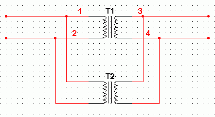
this is what i was try to tell you with the T1 T2 and so on
 

It seems still wrong.

That's what I suggested (using two transformers)
90_1212647042.gif


Sounds as you try hard to confirm Audiogurus statement!
 
yes i was just trying to show the other people what i was talking about befor but thankyou your info really helped. i found some schematics and they where just like yours and what you said. the over load i can see how it would work on every jumper and the main i would put it after the first jumper thanks again
 

there is a paper which states some prerequisities about paralleling of tracos :
http://library.abb.com/GLOBAL/SCOT/scot252.nsf/VerityDisplay/C1256B3C00492DA685256DDD006F2626/$File/1LUS010001-LFE_ParallelOperTrans.doc

worth to read it before when following this way .
 

Status
Not open for further replies.

Similar threads

Part and Inventory Search

Welcome to EDABoard.com

Sponsor

Back
Top