Continue to Site

Welcome to EDAboard.com

Welcome to our site! EDAboard.com is an international Electronics Discussion Forum focused on EDA software, circuits, schematics, books, theory, papers, asic, pld, 8051, DSP, Network, RF, Analog Design, PCB, Service Manuals... and a whole lot more! To participate you need to register. Registration is free. Click here to register now.

measure the current of a motor dc

Status
Not open for further replies.

tictac

Full Member level 5
Joined
Oct 22, 2006
Messages
297
Helped
3
Reputation
6
Reaction score
3
Trophy points
1,298
Location
Polland
Activity points
3,572
Hi
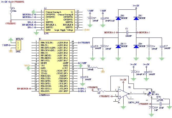
I want to measure the current of a motor dc.I use l298 and
atmega16 and one 1 ohm resistor for that,and also one opamp
for measuring the voltage of the resistor and produce single-
end voltage.the output of the opamp is connected to ADC of
micro.also I connect Enable pin of l298 to the PWM pin of
micro.when I use pwm with maximum number(OCR1A=0x3ff),there is
no problem ,and I can see the current of motor in lcd with
fix value,but when I use pwm in lower value(like
OCR1A=0xff),the value of current doesnt fix,and change very
abnormal.
I use diffrent power supply for motor and l298.

please help me
by regards.
 

1) estimate your maximum current for this motor
2) calculate max. voltage across yout measurement resistor based on this max current (in item 1)
3) compare to you ADC max input range, also consider your OpAmp buffer gain, they all must fit in
4) calculate resolution of ADC, compare to changes you want to measure
5) when you send lower PWM value do you measure current/voltage on resistor ? is it hardware or firmware problem ?
 

    tictac

    Points: 2
    Helpful Answer Positive Rating
Hi tictac,

I'm a little unclear as to the problem you're having. Would it be fair to say this is a summary:

When you measure the current at high duty cycles (for example 95%), you get a steady result, but at lower duty cycles (like 25%) you get un-predictable results?

If so, that's probably just because the motor control input isn't DC (i.e. it's a sinusoid that is effected by the square wave you're putting into it).

Let me know if this is the problem and I can suggest a fix for it.
 

    tictac

    Points: 2
    Helpful Answer Positive Rating
Hi BoBtHePlUmBeR
thank you for your answer.
yes ,you guess correctly.I havnt fix current measuring at low duty cycle.perhaps it is because of pwm .I dont know

by regards.

Added after 2 minutes:

Hi Zman
perhaps it is a noise.I dont think it is a firmware problem,because I can read fix number of adc at high duty cycle.

by regards.
 

OK, well I think I know what your problem is: You're PWM'ing the motor, so you are reading the current either when it is on, off, or some transient in between. This will even out more as you get larger duty cycles (say >90%), which is why you're observing the current as being unstable.

My suggestion is to filter your signal. This will smooth it off significantly, but will add some extra lag into your system, so you will have to have a tradeoff between the filter speed and the filter ripple voltage. You can also improve this to some degree by increasing your PWM frequency.

You've already done most of the hard work. From your 1 ohm resistor you have an op amp which feeds into the ADC. Rather than feeding it in directly, make up an RC lowpass filter before feeding it into the ADC. If you choose a cutoff value of say 10 times less your PWM frequency, you should notice a MUCH smoother waveform. If you need help getting values, let me know what frequency your PWM is running at and I can work out some values for you.
 

    tictac

    Points: 2
    Helpful Answer Positive Rating
Hi
I use fast pwm top=03FF with 10.800 KHZ .
I write C code with code vision.
 

Hi tictac,

I'm not familiar with the LM741 without the BC560A on its output, so I'll submit a simplified solution and maybe you can extrapolate what you need from it. Basically I've added a resistor and capacitor at the output of the amplifier to smooth out the waveform. As I said before - this will create some lag in the signal, but with a cutoff of around 400Hz, it shouldn't be too bad...
 

    tictac

    Points: 2
    Helpful Answer Positive Rating
Hi BoBtHePlUmBeR
Thank you so much
does it need special opamp?
at first I study AN894 from microchip about high-side and low side resistive current measurement,I try both of them,but I cant take any good response,in this app note ,notes that a special opamp(such as auto-zero) must be used,I didnt find any of this opamp.
by regards
 

On Page 7 of that app note there is a specific reference to removing emi noise, where on page 8 (figure 9) they have incorporated emi filtering, as well as signal filtering and gain - this is probably the best option for you if you have the components and can work out the R and C values. If not, just go with the circuit in figure 8 and add the passive RC configuration that I put on the diagram previously (should do the same sort of job).
 

    tictac

    Points: 2
    Helpful Answer Positive Rating
I have this experience driving an array of leds with pwm controller and constant current. I fix it with a 2th order Pasive RC filter like BoBtHePlUmBeR is suggesting.

Calculate the filter with the pwm frecuency and make a media in the ADC Microcontroller because the filter is not the best for the velocity of the clock as you will see in your oscilloscope.

Eng. Canó
Dominican Republic.
2007
 

thank you BoBtHePlUmBeR so much
thank you for your answer.
but it doesnt fix, LSB=200
I couldnt find such opamp that work well

I now test one hall effect sensor ,because I dont have time,later I should test previous way (low side,high side)
by regards
 

Status
Not open for further replies.

Part and Inventory Search

Welcome to EDABoard.com

Sponsor

Back
Top