s_cihan_tek
Full Member level 2
how to get rid from voltage spikes
Hi everyone,
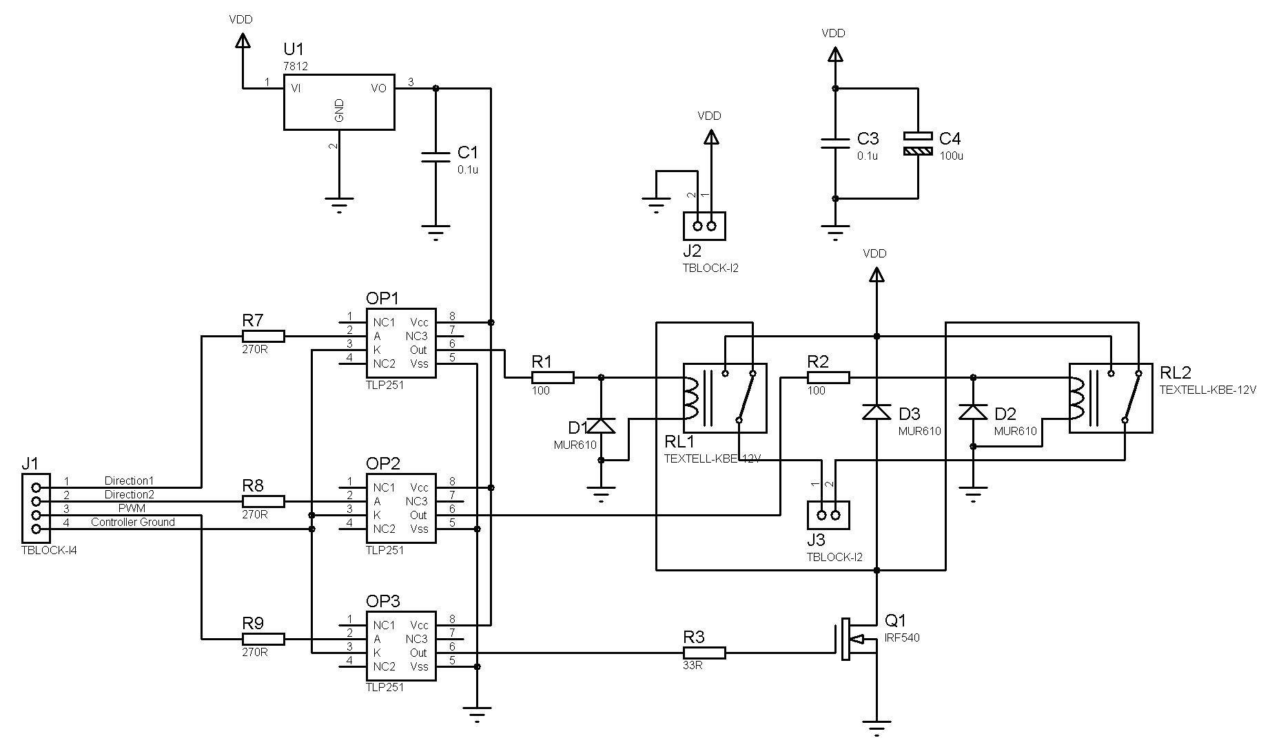
I'm trying to make a dc motor driver circuit using 2 relays for direction control and one MOSFET for switching. The schematic of my circuit is given below. The motor is connected to the connector J3 on the schematic. The supply voltage is 24V and the motor draws 6A of current at this voltage.

The problem i faced here is voltage spikes and oscillations across the MOSFET and the DC motor. Also the motor and its parallel diode gets hot even they're rated for a much higher working current and voltage. I tried to connect capacitors paralel to the MOSFET and the spikes are gone but this time the turn-on time of the MOSFET increased and both the motor and its parallel diode got hot. I also checked the ground rail and there wasn't any oscillations.
Here is a .doc file which contains the waveforms i measured with the oscilloscope:
**broken link removed**
I took these measurements from the circuit when there wasn't any capacitors connected across the MOSFET.
Especially the voltage across the motor is very bad. What can be reason of this and how can i get rid of these spikes and oscillations?
I also tried to put a TVS across the MOSFET and it clamped the oscillations but this time the TVS heat up and burned.
Hi everyone,
I'm trying to make a dc motor driver circuit using 2 relays for direction control and one MOSFET for switching. The schematic of my circuit is given below. The motor is connected to the connector J3 on the schematic. The supply voltage is 24V and the motor draws 6A of current at this voltage.
The problem i faced here is voltage spikes and oscillations across the MOSFET and the DC motor. Also the motor and its parallel diode gets hot even they're rated for a much higher working current and voltage. I tried to connect capacitors paralel to the MOSFET and the spikes are gone but this time the turn-on time of the MOSFET increased and both the motor and its parallel diode got hot. I also checked the ground rail and there wasn't any oscillations.
Here is a .doc file which contains the waveforms i measured with the oscilloscope:
**broken link removed**
I took these measurements from the circuit when there wasn't any capacitors connected across the MOSFET.
Especially the voltage across the motor is very bad. What can be reason of this and how can i get rid of these spikes and oscillations?
I also tried to put a TVS across the MOSFET and it clamped the oscillations but this time the TVS heat up and burned.