Continue to Site

Welcome to EDAboard.com

Welcome to our site! EDAboard.com is an international Electronics Discussion Forum focused on EDA software, circuits, schematics, books, theory, papers, asic, pld, 8051, DSP, Network, RF, Analog Design, PCB, Service Manuals... and a whole lot more! To participate you need to register. Registration is free. Click here to register now.

Normal Keypad Interface to PC Via PS2

Status
Not open for further replies.
Hi,

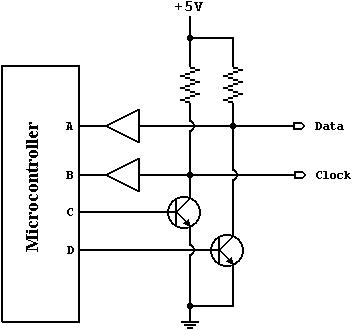
I already done the Host-to-KB code. Can you check for me? How can we test ourself?
Code:
#include <reg51.h> 

#define BYTE (7)
#define PARITY (1)
char D_Bus[BYTE+PARITY]={0};

sbit clockpin = P3^2; 
sbit datapin  = P3^7; 

void sendbit(char b){ 
char i; 
    datapin=b; 
     for (i=0; i<5; i++); // Clock Time for Hi 
    clockpin=0;      
     for (i=0; i<9; i++); // Clock Time for Lo 
    datapin=b; 
    clockpin=1;      
} 

void D_Buffer(void)
{
	char nbit=0, i=0;
	
	do
	{
		clockpin=1;
		for (i=0; i<5; i++) // Tck - Clock Time for Hi
		{
			D_Bus[nbit] = datapin;
		}
		clockpin=0;
		for (i=0; i<9; i++) // Tck - Clock Time for Lo
		{
			D_Bus[nbit] = datapin;
		}
	}while(nbit++ <= 8);

	sendbit(1); // HI
	sendbit(0); // ACK
}

void Host_To_Drive(void) interrupt 0
{
	char i=0;

	while(!INT0);
	datapin=0;

	clockpin=1;		     // Raising Edge
	for (i=0; i<5; i++); // Tck - Clock Time for Hi

	clockpin=0;			 // Falling Edge
	for (i=0; i<2; i++); // Tck - Clock Time for Lo

	D_Buffer();
}

void main (void) { 

	IT0 = 0;
	IE0 = 0;
	EX0 = 1;
	TF0 = 0;
	EA  = 1;

	while(1)
	{

	}

Thank You.
 
Check and test this code (I just write it on NotePad)
Code:
#include <reg51.h>

sbit clockpin = P3^2;
sbit datapin  = P3^7;
byte PCdata   = 0;

void sendbit(char b){
char i;
     datapin=b;
     for (i=0; i<5; i++); // Clock Time for Hi
     clockpin=0;     
     for (i=0; i<9; i++); // Clock Time for Lo
     datapin=b;
     clockpin=1;     
}

char recvbit(char b){
char i;
     for (i=0; i<5; i++); // Clock Time for Hi
     i = datapin;
     clockpin=0;     
     for (i=0; i<9; i++); // Clock Time for Lo
     clockpin=1;    
     return i<<7; 
}

void Host_To_Drive(void) interrupt 0
{
char i;
   EX0  = 0;     // disable interupt
   recvbit();    // start bit
   PCdata = 0;
   for (i=0; i<8; i++){
        PCdata += recvbit();
        PCdata >>= 1;
        }
   recvbit();    // parity bit
   sendbit(1);
   sendbit(0);
   sendbit(1);
}

void xmit(char a){
char i,mask;
char parity;
    parity = 0;
     sendbit(0);            // start bit
     mask = 1;
     for (i=0; i<=8; i++) { // shift right -> b0.. b7
         if (a & mask) {sendbit(1); parity++;}
         else sendbit(0);
         mask <<= 1;
     }
    parity &= 1;         // least significant bit only
    sendbit(!parity);    // convert to odd parity
    sendbit(1);          // stop bit
} 
void main (void) {

   IT0 = 1;
   EX0 = 1;
   EA  = 1;

   while(1)
   {
    if PCdata!=0 {xmit(0xFA); PCdata=0; EX0=1;}
   }
}
 

    Help

    Points: 2
    Helpful Answer Positive Rating
Hi,

I'm not so understand the recvbit() function. Actually recvbit() doesn't carry any value rite?
i try to use software simulate the datapin in recvbit(), but the PCdata result not change on Host_To_Drive().
i PCdata
0 C0
1 20
2 D0
3 28
4 D4
5 2A
6 D5
7 2A

How can i test Host-to-KB? How to call the PC sending data to my 8051? Then how can i test/know the result after the PC sent data?

Thank You.
 

There is mistakes on last code, check this one:
Code:
char recvbit(void){
char i,databit;
     // MCU generate clock, but PC transmit data bit
     for (i=0; i<5; i++);       // waiting for data stable
     databit = datapin;         // get PC data bit to i
     clockpin=0;                // negative going edge
     for (i=0; i<5; i++);       // PC will transmit new data bit
     clockpin=1;                // clockpin standy state
     return databit<<7;         // shift to bit 7 -> return value to caller
}

void PCsendCommand(void) interrupt 0
{
char i;
   EX0  = 0;                    // disable interupt
   recvbit();                   // start bit
   PCdata = 0;                  // if PCdata!=0 -> there is new byte from PC
   for (i=0; i<8; i++){
        PCdata >>= 1;           // shift right 1 position
        PCdata += recvbit();    // new data bit inserto into 7th position
        }
   recvbit();                   // parity bit, at this case I ignore it
   sendbit(1);                  // reply acknowledge bit
   sendbit(0);                  // reply acknowledge bit
   datapin = 1;                 // datapin standby state = 1
}

21_1170323388.gif


How can i test Host-to-KB? How to call the PC sending data to my 8051? Then how can i test/know the result after the PC sent data?
When PC startup, the LEDs on keyboard blinking for a moment. That time the PC send command to turn on and off keyboard's LED.
Connect you device to PC PS/2, start the PC and test your code.
 

    Help

    Points: 2
    Helpful Answer Positive Rating
Hi,

I already try my keypad. I use Switchs to switch the Keyboard and Keypad clk n data signal. Initialize i switch it to Keyboard, but after OS i switch it to Keypad for testing.

I found out one thing is our clk is INT0 pin while we sent data to host the clk-pin Lo will interrupt occur. That's i'm using Keil software to simulate it. In practical it still will comeout the result which is Key1=d, Key2=t, Key3=) and following Key will make my pc hang.
But i try to use other pin for clk the result still giving me a same problem, PC hang. Do you know why?

The Keyboard ScanCodes: AT Keyboard Scan Codes (Set3)

Another question. Do we need to add some resisters between PS2 to PC? as the picture showing.

I already attached the code. Please have a look.

Thank You.
 

Hi all,

I was digging the net for details regarding keyboard emulation, i found that this link is much useful hence joining it. Before starting the emulation I have gone through some links specified below. I have observed the keyboard data transmission protocol by refering some sites and parallely hooking my CRO probes to the KBD_DATA and KBD_CLK line of my keyboard when transmitting some data. I am having problems in emulating the keyboard controls. Iam using Atmel's 89C52 MCU. I have checked the timing details but it is not working.

I expect all your help in this regard. iam ready to share my experience observations, codes and will write some program for your 8051 MCU. And this is what i've done till now.

What the MCU will do is send the data corresponding to "a" key to the PC at an interval of 2.5 seconds. Before making the MCU to execute i opened a notepad and connected my Keyboard and typed character "a" in the keyboard. Observed the timing details and the data transmission pattern and in a similar way i'd programmed my MCU to send the code. i.e 2 bytes of code F0 and 1C. I removed the PC KBD's Data and clk line and connected the same from PC to my MCU . when the probes are hooked to the data and CLK line. i could get the same timing pulses as that sent by the keyboard but the character is not appearing on the notepad. I once again reconnected the PC kbd and it started typing characters, but when the same signal is gven by MCU it is not working. Can some one explain this ?. In some site they have mentioned that the kbd data and clk lines are opencollector. The 89C52's port P0.0- DATA line, P0.1 -CLK line are also open collector and i've used them but in vain. Ihave connected 4.7 K resistors between DATA and Vcc, CLK and Vcc. PLease do help me. the following sites i referred for Knowing about PS/2 Communication.


**broken link removed**

**broken link removed**

As "help" is also trying to interface "his 4X4keyboard" to the PC, i think iam also sailing in the same boat. Also i appreciate the work of IanP and Budhy.

I feel that using assembly language will be much better as i read from the notes that the PS/2 Protocol requires strict timing requirements.

I have written some code in assembly for transmitting data and i need some of all your time to help me successfully emulate the keyboard operation.
 

help,
You code and schematic I'll discuss later to night, but at this moment I think you have to read about Make Codes, Break Codes, and Typematic Repeat on page 10 of my attached document, I got this document from this site, but I edited it as a small booklet :
PS/2 Mouse/Keyboard Protocol
From Computer-Engineering
• Source: **broken link removed**
• Author: Adam Chapweske
 

    Help

    Points: 2
    Helpful Answer Positive Rating
Hi,

Thank for your booklet.

I think i'm miss the typematic rate and delay using the "Set Typematic Rate/Delay" (0xF3) command function. But this comman is send by PC, am i right?

..the typematic delay, which is the short delay between the first and second "a",...
I have no idea on this part.

Is it we have to defines the typematic the Repeat-Rate and Delay table in our code? So we have to do the checking for repeat and delay command that pc send to keypad?
Let say if the pc send the command is 00010010b so we know it is Repeat-Rate(2h)=24cps Delay(01b) = 0.5sec. Is it like this?

Thank You.
 

m.42 wrote:
I have written some code in assembly for transmitting data and i need some of all your time to help me successfully emulate the keyboard operation.
Welcome m.42, send your assembly code and we discuss it together.

Added after 15 minutes:

Basically your code is alright, there is no error.

int0 is OK, as long as you disable the interrupt when clocking

Another question. Do we need to add some resisters between PS2 to PC?
No

I use Switches to switch the Keyboard and Keypad clk n data signal. Initialize i switch it to Keyboard, but after OS i switch it to Keypad for testing.
I think the problem is here.
Make this experiment. When Windows is running, unplug ke keyboard and plug it again. what happen with your keyboard? Windows can't recognize the keyboard any more!
I think you have to write the complete code for Keyboard initialized conversation, to make your keypad as real keyboard!

Expand this function void initialize(void);
 

    Help

    Points: 2
    Helpful Answer Positive Rating
Actually iam trying to do what a keyboard will do to a PC, but the only difference is that instead of keyboard sending the command my microcontroller will send the signal. before reading any manual i hooked my probes on the data and clk of the PS/2 line and observed the pattren in both the lines noting down carefully the timing details.The same thing i had done with my 89c52 microcontroller. the data = p0.0 and clk= p0.1. i got the info that since the MCU's PORT 0 is open collector and most of the sites which i referredtold that only open collector outputs need to be connected to the pc's kbd data and kbd clk lines. hence i didn't use any details special interface between the MCU's pins and the ps/2 lines. other than a simple 4.7k pull up resistor for both the lines. what "help" is also doing the only difference. To solve my final solution of emulating the keyboard, i put forth my immediate objective as to emulate only the key "a". i opened a notepad and hooked my probes for clk and data signals. i observed 2 bytes of transmission ( by copnnecting the kbd). fig 1 will give the screen shot of my signal observed in the
CRO.The remaining figs are just the enlarged or close up view of the signals -one byte per screen. For this i have assumed the following conditions.
1. The data and clk lines are high. that is, the pc is not sending any commands to my kbd.
2. The MCU is not checking the status of data and clk lines before sending the bytes.
now i have diconnected the keyboard's data and clk line from the pc and connected the microcontroller's p0.0 (data) and p0.1(clk) line to the PS/2 connector. after power up for every 4 seconds the mcu will transmit two bytes. Iam sending my assembly code, figures info etc.

I think iam doing a part of what help is doing. the only difference being he's scanning "his keyboard" while iam simply transmitting two bytes. please do help me.
 

help wrote:
Do we need to add some resisters between PS2 to PC?
m.42 wrote :
The same thing i had done with my 89c52 micro controller. the data = p0.0 and clk= p0.1. i got the info that since the MCU's PORT 0 is open collector and most of the sites which i referred told that only open collector outputs need to be connected to the pc's kbd data and kbd clk lines. hence i didn't use any details special interface between the MCU's pins and the ps/2 lines. other than a simple 4.7k pull up resistor for both the lines. what "help" is also doing the only difference. To solve my final solution of emulating the keyboard, i put forth my immediate objective as to emulate only the key "a". i opened a notepad and hooked my probes for clk and data signals. i observed 2 bytes of transmission ( by connecting the kbd).

m.42 circuit:
28_1170776735.gif


Compare the following 2 circuit, then you'll agree actually MCS51's Port 1 or 3 is suitable direct connect to PS/2 port.

54_1170775165.JPG

Figure 1 of PS/2 Mouse/Keyboard Protocol From Computer-Engineering
General open-collector interface. Data and Clock are read on the micro controller's pins A and B, respectively. Both lines are normally held at +5V, but can be pulled to ground by asserting logic "1" on C and D. As a result, Data equals D, inverted, and Clock equals C, inverted.

4_1170820477.gif

Figure 2 MCS51's Port 1 & 3 internal Circuitry

Note :
Buffer on Data Input and Clock Input of Figure 1 is equivalent with B2 of Figure 2.
Two transistor of Figure 2 is equivalent with MOSFET of Figure 2
 

    Help

    Points: 2
    Helpful Answer Positive Rating
Yes first i thought that 8051 MCU has the open collector pins and didn't use transistor connection. I didn't find any difference whether i use the transistor or connecting the pins directly. I knew that it'll take some time for you to read the code but do ask any me if you r not clear with my steps.i've used keil ide uvision V3.50. Latest frm keil but its evaluation version.in this it has the option to see the waveform while debugging.
 

At last i had seen the my MCU TYPING

thanks to all . "At last i had seen the my MCU TYPING" on the notepad. i tried the following sequence as said in one of the pdf document attached BY BUDHY. Following this i'll attach the related docs. for your referral. This is the first step of my fairly big project. I hope i can help "help" if he gives me the schematic. The one thing which he attached doesn't contain any details regarding which pins he'd connected "his 4X4 key pad" and i can do it in assembly only. I hope you can call assembly routines from c program thinks so. so " help " get me the details reg the kbd_data , kbd_clk pins from your MCU and your key pads - connected to pins of MCU.


Example: What sequence of make codes and break codes should be sent to your computer
for the character "G" to appear in a word processor? Since this is an upper-
case letter, the sequence of events that need to take place are: press the
"Shift" key, press the "G" key, release the "G" key, release the "Shift" key. The
scan codes associated with these events are the following: make code for the
"Shift" key (12h), make code for the "G" key (34h), break code for the "G"
key(F0h,34h), break code for the "Shift" key (F0h,12h). Therefore, the data
sent to your computer would be: 12h, 34h, F0h, 34h, F0h, 12h.
 

Re: Here is thefinal firmware For emulating PC KEYBOARD

SEE ATTACHMENT FOR THE CODE, ASSEMBLER. TESTED
 

help mail me:
I already try as you say. Let my Keypad initialized conversation when pc startup. After in the OS i open the notepad try to press the keypad. The 8051 can't generate the clock and nothing come out in the notepad. I attached 3 Key #1 #2 #3 sample waveform for you in Excel file. Please have a look.
Try this new method to test your project. We place the board parallel with regular keyboard-PC connection, as this :
9_1171511884.gif

this configuration will skip Keypad initialized conversation when pc startup, the regular keyboard will do that[/quote]
 

    Help

    Points: 2
    Helpful Answer Positive Rating
Hi,

I tested the new method. There are 2 problems:
1)
If i pressed the key either Keyboard or Keypad, my PC will hang (and sound "ti ti..")
2)
Because of this i try to simulate the initialize() function with LED.
Code:
void initialize(void){
     LED = 0x00;
     xmit(0xFA); PCdata=0; EX0=1;
     LED = 0xFF;
}
You can see the result from the Excel. The initialize() function alway called without pressed any key. Then cause the LED active. Is it something wrong with the INT0 pin?

Thank You.
 

help,
I have no idea. Would you like to send your complete code and schematic?
 

Hi budhy,

Thank for your reply.

The problem that i face on M2:
We place the artificial-keyboard parallel with regular keyboard-PC. With this connection it is trick to make sure the PC will recognize our keyboard is inteface.

After in OS. Open notepad. I try press something on my artificial-KB, there are only 2 to 3 key is ok, but other will comeout different thing and sound. And some of the key will make PC hang.

Code:
if (PCdata) initialize();
In our code, this line will be access when PCdata have data. Also because of
Code:
clockpin = P3^2; // /INT0 (external interrup)
I suspect initialize() function this routine will be access when i press any key on artificial-KB. So, i try use LED to indicate that. When key pressed there is a pulse on LED.

Thank You.
 

Status
Not open for further replies.

Part and Inventory Search

Welcome to EDABoard.com

Sponsor

Back
Top