Continue to Site

Welcome to EDAboard.com

Welcome to our site! EDAboard.com is an international Electronics Discussion Forum focused on EDA software, circuits, schematics, books, theory, papers, asic, pld, 8051, DSP, Network, RF, Analog Design, PCB, Service Manuals... and a whole lot more! To participate you need to register. Registration is free. Click here to register now.

Help identify ferrite bead on a sound card

nunoalex

Newbie level 4
Joined
May 11, 2024
Messages
6
Helped
0
Reputation
0
Reaction score
0
Trophy points
1
Activity points
51
Hi everyone

First post here :)
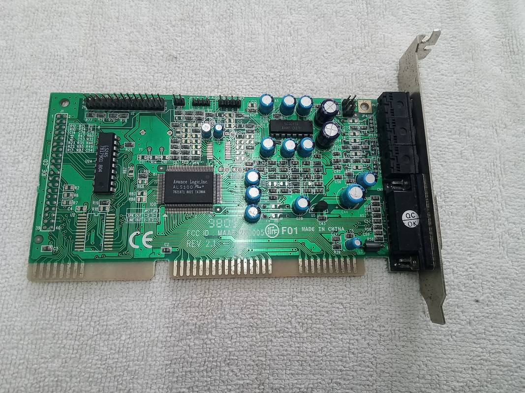
I love vintage computers and sometimes I come across salvaged parts and I try to repair.
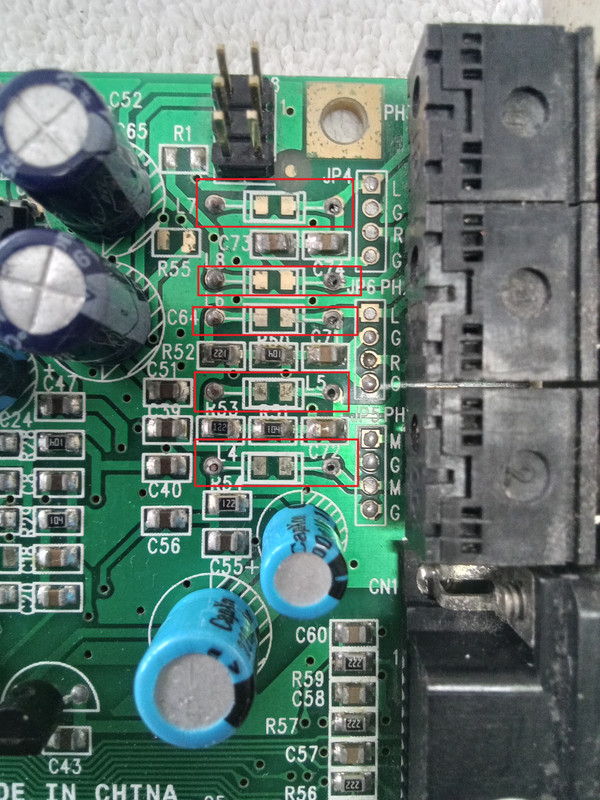
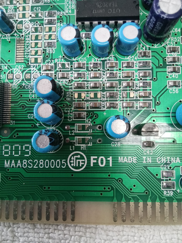
I got a nice sound card but someone tore the ferrite beads for scrap... unreal
Is there a way to know what values this beads have so I van buy replacements ?

20240511-150115.jpg


20240511-150126.jpg


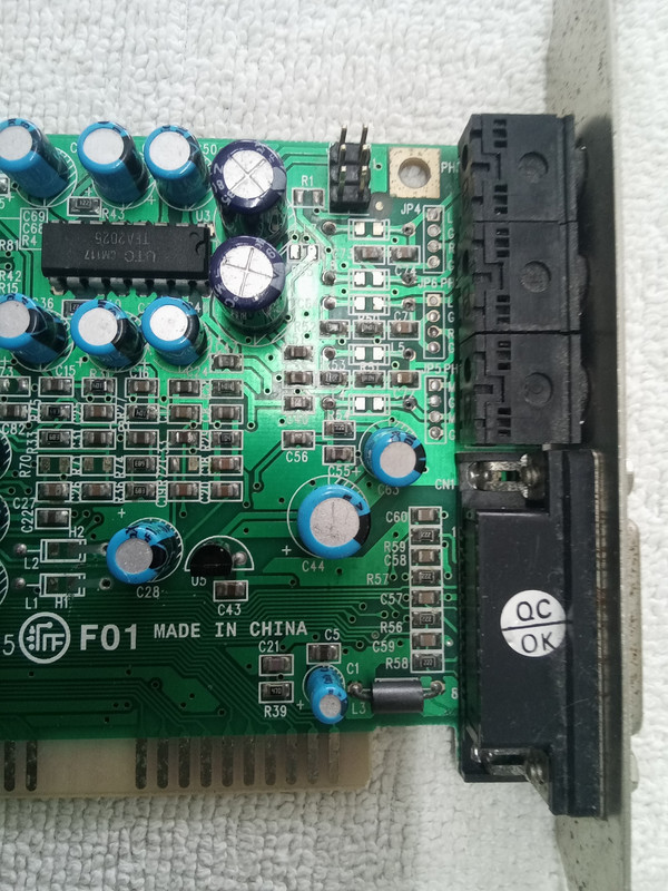
Only L3 has survived but I have no idea if it is of the same value as the others and even if it was I dont know how to measure it

I dont know if they are to filter the power rail noise +5v and +12v or if they are on the audio path (or both)
But since they zre so many and the card really only takes 2 voltages I am more inclined for audio (analog) noise suppression

Can someone help me find the right replacement ferrites ?

Thank you

Nuno Alex
 
Hi,

ferrite beads are not useful for audio frequencies.
Thus I rather guess they are used in the power (including GND) path.
Maybe it is used to connect A_GND with D_GND.

In either case it is used for HF frequencies in the high MHz.
And the circuit will probably work if the ferrite bead is replaced by a piece of wire. (for sure it is recommended to install a ferrite bead).

Ferrite beads are rather low impedance at DC (low milliOhms), and they may go up to several 100 Ohms at many Megahertz. They are no precision devices, they are not critical.
So as long as they can carry the DC current you need .... you may chose a bead with some tens of Ohms at high frequencies.

Klaus
 
Ferrite beads at audio I/O connectors are most likely there to keep EMC standards, no necessarily required for repair.
You can select ferrite bead by size. Most manufacturers don't have more than 2 or maximal 3 different ferrite materials for beads on leads, you can choose the material with highest impedance.
 
Hi,

ferrite beads are not useful for audio frequencies.
Thus I rather guess they are used in the power (including GND) path.
Maybe it is used to connect A_GND with D_GND.

In either case it is used for HF frequencies in the high MHz.
And the circuit will probably work if the ferrite bead is replaced by a piece of wire. (for sure it is recommended to install a ferrite bead).

Ferrite beads are rather low impedance at DC (low milliOhms), and they may go up to several 100 Ohms at many Megahertz. They are no precision devices, they are not critical.
So as long as they can carry the DC current you need .... you may chose a bead with some tens of Ohms at high frequencies.

Klaus
Thank you so much for your kind reply

you are right this component would probably have a very low impedance at audio frequencies anyway...

I will go to digikey and choose a ferrite with similar dimensions and something like 50 to 100 ohm at 100 mhz

all the best

Nuno
 
Ferrite beads at audio I/O connectors are most likely there to keep EMC standards, no necessarily required for repair.
You can select ferrite bead by size. Most manufacturers don't have more than 2 or maximal 3 different ferrite materials for beads on leads, you can choose the material with highest impedance.


Thank you so much for your kind reply

Indeed looking at the frequencies this devices are rated to they are almost a short at audio frequencies...

I will go to digikey and choose a ferrite with similar dimensions and something like 50 to 100 ohm at 100 mhz

all the best

Nuno
 
Do you know if the parts were not populated by OEM or depopulated by someone for sure?


If so, circle the pads and attempt to duplicate the partial schematic. For audio the main purpose is to reject AM signals from getting demodulated into audio or SMPS ripple filter near 1 MHz, high impedance 805 parts maybe with > 500 mA

Below is 8 kohm at 100 MHz LC resonance and 0.7 ohm at DC, so you can compute the LC values.

1715558324018.png
 
Do you know if the parts were not populated by OEM or depopulated by someone for sure?


If so, circle the pads and attempt to duplicate the partial schematic. For audio the main purpose is to reject AM signals from getting demodulated into audio or SMPS ripple filter near 1 MHz, high impedance 805 parts maybe with > 500 mA

Below is 8 kohm at 100 MHz LC resonance and 0.7 ohm at DC, so you can compute the LC values.

View attachment 190744

Hi!
Thank you for the help

They have been tore alright... pictures of this sound card on the internet clearly show them
7 ferrites, some pads went along with them .. fortunately the vias seems to be intact and they only connect on the back
I have no idea why... this component doesnt have any copper or precious material.. maybe someone needed them for something else
I really would like to bring this little bugger back to life, there are also a few traces broken on the back


20240513-180524.jpg


20240513-180514.jpg
 
I am reading they are all 47 uH, but no details were give. They would be the same size as 1/4 resistors, but you can also choose 805 SMD packages.
No idea on DCR values.


View attachment 190775


Thank you Tony

I have read on VOGONS that one of them was tested to .850uH and on some schematic it was stated 1uH
It is very confusing, my skill level usually falls back to replace capacitors and resistors...

So 47uH will make it 30k ohm at 100 mhz... that's rather high no ? I have not seen such component on digikey...

Z = 2 * Pi * 100mhz * 47x10-6 ... am I wrong ?

I just have the feeling that if i dont replace it with the right value there will be noise on the audio output... and yeah this is a SOUND card :)

thank you
 
It is not a ferrite bead (FB) but it is used to comply with FCC Part B to reject IDE logic transition noise up in the 100 MHz range so that when external linear power amps have non-linear effects with RF, the demodulation interferes with the audio signal.

The datasheet has a BOM , or "bill of material" for this shown in >/AS100-L-M S100DM2.pdf file near the end, p6-12, as I showed.

It says it is an epoxy thru-hole 47 uH inductor, and L is the reference designator (REF DES) for inductor. Guess what it is for ferrite bead? It could be identified as FB# or could be L . The 1st example I found in their documents was in the ALS100 folder is shown below.

1715695166571.png
( except I could not read the .doc files made by Adobe Framemaker)

It will work with a jumper on the SMD pad, until you get some inductors.

In fact, it is the only BOM in your link of manuals with an L5, many others have L1 to L4 of 10 uH.
FB's are cheaper lossy ceramic materials with a mix of metal, magnetic and dielectric to simulate a lossy inductor with fairly low R but much looser tolerances.

Considering my background , and others here (read) and yours, why would you doubt my previous answer compared to your online search?

I too love these Win95 vintage audio synth cards. Win95 from Packard Bell had a huge suite of useful features, speakerphone, modem, VOIP, phone auto message folders, custom voice messages, MIDI music synth, and DC coupled electret mic inputs with no pop sound or DC offset instead of the cheap AC coupled types now.
 
Last edited:

LaTeX Commands Quick-Menu:

Part and Inventory Search

Welcome to EDABoard.com

Sponsor

Back
Top