Continue to Site

Welcome to EDAboard.com

Welcome to our site! EDAboard.com is an international Electronics Discussion Forum focused on EDA software, circuits, schematics, books, theory, papers, asic, pld, 8051, DSP, Network, RF, Analog Design, PCB, Service Manuals... and a whole lot more! To participate you need to register. Registration is free. Click here to register now.

No Voltage output in the simulation

BillyTheBob

Newbie level 4
Joined
May 1, 2024
Messages
7
Helped
0
Reputation
0
Reaction score
0
Trophy points
1
Activity points
56
Hi. I'm new, so, sorry for the mistakes I make (whether in the forum or when talking because I'm not that good at English).

I'm trying to replicate this circuit (from this link: https://headwizememorial.wordpress....e-ended-otl-amplifier-for-dynamic-headphones/) in Proteus to try to understand/see how things work etc.
1714567442868.png

---------------------------------------
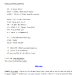
But for the second part of the power supply, there is no output voltage shown:
1714567578804.png

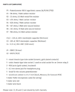
I tried to match every component as much as I could.
What can I do to have voltage output on C5(1) or is it supposed to look like that, what am I missing/did I miss?
I don't have a strong understanding of every component yet. Sorry if it wasn't relevant or was a very broad question.

tr1(p1) and tr2(p2) are 220 volt 60hz
 

Attachments

  • 1714567927300.png
    1714567927300.png
    112.3 KB · Views: 34
  • 1714567958454.png
    1714567958454.png
    95.3 KB · Views: 32
I don't like simulators with input sources coming from nowhere. TR2 secondary voltage is however measured as NAN (not a number, e.g. float division by zero). Looks like a simulator bug, or very strange defined input voltage (e.g. DC voltage).

Perhaps there are some Proteus fans online who can tell if it's a known problem or how it's possible.
 
Hmm. I just realized that I was supposed to use polarized capacitors instead of normal ones I guess

Edit: No, still same :(
 
Hi,

sometimes simulations have a problem with floating signals. Here: the output of TR2. A solution could be a high ohmic resistor to GND.

Klaus
 
Transformer definition is wrong. Winding ratio has to be set by ratio of primary and secondary inductance L1/L2 = (n1/n2)^2. E.g. L1 = 8.1 H, L2 = 0.1 H
Coupling factor should be high, e.g. 0.99
 
1714602746966.png

I tried to debug step by step. Tried to change the bridge (I also just learned that 4-diode thing called bridge xD. I have a long way). I tried to clean everything else on the right of the transform. And started to add things one by one until I stopped getting Volts. It was the Voltage regulator. I was using ld1117D. But then I googled for "proteus linear voltage regulator simulate", and saw LM317 on one of the titles. So I tried it, and for now seems that there is at least some voltage (C11(1)), but not sure if it's the one that I should be getting.

Short: Changing the voltage regulator provided some voltage :D
 
Last edited:
Transformer definition is wrong. Winding ratio has to be set by ratio of primary and secondary inductance L1/L2 = (n1/n2)^2. E.g. L1 = 8.1 H, L2 = 0.1 H
Coupling factor should be high, e.g. 0.99
Does this look alright?
AC volts show 17.3-17.4V (17.2V with coupling factor 0.99) instead of 14.7V.
I'm just happy I have some voltage at least LOL.

1714603545633.png
1714603193759.png
 
"1/9" coupling factor may be both a syntax error if it does not support math functions" Thus "not a number"

and a functional error. (0.99 is closer to desired reality)

Why is Neutral or return not specified?

It ought to be a differential source with no ambiguous single-ended source , then you won't have to add a secondary ground = 0V ref to the schematic.

By the way( BTW), 220V 60 Hz is not a standard that I know for single ended to ground.

We have 120Vrms Line to Neutral (almost~0V) or 240 Vrms differential (line to line)= L1 to L2 using 60 Hz in North America coming from a split distribution transformer where it is earthed.

Which country is yours? You want use the same source for TR2 as TR1 AND must be shown on the schematic.
 
Last edited:
Why is Neutral or return not specified?
Sorry, I don't know what they are, to be honest. I am very very new, not just in the forum xD
By the way( BTW), 220V 60 Hz is not a standard that I know for single ended to ground.
I actually should adjust it for Germany. But the calculations on the website are probably made for wherever the person who designed them lives, so I just gave a bit of a random number. The person who designed the circuit says he got the components in the USA. So it should be 120V / 60Hz as you said, I guess.
1714640735913.png
 
Hi,

Germany is 230V AC RMS (L-N), 50Hz.
(so none of your voltages and frequencies is correct)
And we use the three phase system with 120° shift phase to phase resulting in 400V AC RMS (L-L). Neutral is connected with Earth-GND.


Chaos.
As well as with your junction dots. Some are where they don´t belong, some are missing where they belong.
Usually the software sets them automatically to the right place.

Klaus
 
Germany is 230V AC RMS (L-N), 50Hz.
(so none of your voltages and frequencies is correct)
And we use the three phase system with 120° shift phase to phase resulting in 400V AC RMS (L-L). Neutral is connected with Earth-GND.
So, I should play with the transformer to have the same output voltage from the transformer to not touch any other component I guess. This way I'd have to deal with only 1 part. But not sure if it still would be efficient.


Chaos.
As well as with your junction dots. Some are where they don´t belong, some are missing where they belong.
You know, when I actually take a second look at it, it's quite funny actually lol xD. I didn't pay attention that much (1, I'm new, and didn't know I should (though being more in line/order is better for down the road), and 2:) my main purpose is to play with things on the Proteus. But will try to be more careful next time. Thank you for pointing that out, :D
 

LaTeX Commands Quick-Menu:

Part and Inventory Search

Welcome to EDABoard.com

Sponsor

Back
Top