engr_joni_ee
Advanced Member level 3
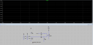
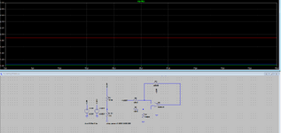
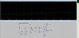
Hi, I am trying to run the simulation in LT Spice but I am not sure what is missing.
Can someone please have a look and suggest what can be done to run the simulation.

Can someone please have a look and suggest what can be done to run the simulation.