Continue to Site

Welcome to EDAboard.com

Welcome to our site! EDAboard.com is an international Electronics Discussion Forum focused on EDA software, circuits, schematics, books, theory, papers, asic, pld, 8051, DSP, Network, RF, Analog Design, PCB, Service Manuals... and a whole lot more! To participate you need to register. Registration is free. Click here to register now.

BTS50080-1TEB not working

Status
Not open for further replies.

hudyrock

Newbie level 4
Joined
Sep 20, 2021
Messages
7
Helped
0
Reputation
0
Reaction score
2
Trophy points
3
Location
Liberec, Czech Republic
Activity points
46
Hello,

i have problem with power mosfet mentioned in title. I am using simple schematics:

BTS50080-1-TEB.png


In test circuit I am using halogen light bulb from car as a load (approx 2.7 A). If i set the IN pin (active in low), output is still without power, and pin IS is HIGH. after witching on the IS pin is always HIGH (output circuit open, short to ground and with load).


thank you in advace for your answer.
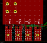
 

Well, it does not work when the pin is directly on the ground also. I made soldered wires dirctly on spare chip i had, just to be sure the chips on pcb are not demaged by heat from a reflow oven so i have minum circuit - power supply directly to Vbb, out directly to light bulb which is grounded. Input pin shorted to gnd directly and 1k resistor on IS, grounded. Multimeter on IS pin. Both outputs 1 and 5 are connected.
 

Hello, no power collapsing, current consumption from ps is around 3 mA. Pin numbering is maybe confusing because pcb is made in kicad, so it was matched afterwards. I am sure the pin numbering is correct, this circuit is so simple i do not know where can be the mistake. Only hint is the IS pin voltage vhen IN is grounded (Vbb).
 

I have 5 of them. 4 on pcb and 1 separately only on wires just to proof the function and every chip has same behaviour. Bulb is working normalny if i place it directly on ps, also tried 10k resistor as a load - same. Pins were tested at first as it is on schematics - trough 10k resistor on IN, then directly to gnd.
 

Hi,

Your schematic is different to the datasheet examples. The datasheet shows IS connected with one series resistor directly to ground. I didn't read extensively but guess a formula is provided to calculate its value for OCP, etc.

What are you doing with the IC tab? I suppose you know it's also a power connection.
 

Hi again,

Can't say I find this a very pleasurable datasheet for people unfamiliar with the device or who just don't like 'fill-in-the-gaps-yourself' puzzles.

Does the truth table mean anything to you (I gave up trying to understand it) regarding what may affect operation? Have you tried to do any maths about the Iout/Is current ratio with the 2.7A out and the 1k resistor (0.5 to 1.5 from a nominal 1 is a big range, 5,000 to 15,000 in the graph) in case that is what is shutting down the device?

Have you considered these points and measured the voltages (and currents) there. It might just be that the voltage on IN is wrong without a transistor or something:

BTS50080-1TEB VbIN and Q1 etc.jpg


I might consider buffering a DMM with an op amp voltage follower, just in case it steals current from voltage measurements and affects anything needing to be measured.
 

    hudyrock

    Points: 2
    Helpful Answer Positive Rating
Hi,

What´s your Vbb voltage?
Where does it come from?
Is there a stabilizing capacitor?

Klaus
 

Well, now i know the problem, my measuring clamps were total garbage. Here is the photo:
kabel.jpg


So I apologize to everyone who's try to help with circuit.

I will go trough the info from d123 and make some measurements, then I will post it here for some conclusion.

Thank You!
 
Status
Not open for further replies.

Similar threads

Part and Inventory Search

Welcome to EDABoard.com

Sponsor

Back
Top