T
treez
Guest
Hi
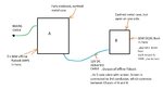
Page 30 of this
says...
Filters that must provide significant levels of attenuation at frequencies above 100MHz, must employ shielding techniques as well. They will not be able to achieve the required performance otherwise.
Is this true?
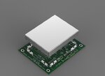
Why does this common mode choke purport to be able to provide attenuation above 100MHz….
Wurth 744841414
…it doesn’t have shielding
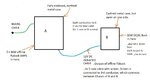
Page 30 of this
says...
Filters that must provide significant levels of attenuation at frequencies above 100MHz, must employ shielding techniques as well. They will not be able to achieve the required performance otherwise.
Is this true?
Why does this common mode choke purport to be able to provide attenuation above 100MHz….
Wurth 744841414
…it doesn’t have shielding