Continue to Site

Welcome to EDAboard.com

Welcome to our site! EDAboard.com is an international Electronics Discussion Forum focused on EDA software, circuits, schematics, books, theory, papers, asic, pld, 8051, DSP, Network, RF, Analog Design, PCB, Service Manuals... and a whole lot more! To participate you need to register. Registration is free. Click here to register now.

Designing a sequence detector of a sequence having 100 bits

Status
Not open for further replies.

fragnen

Full Member level 3
Joined
Apr 3, 2019
Messages
182
Helped
0
Reputation
0
Reaction score
1
Trophy points
18
Activity points
1,299
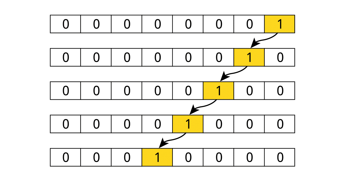
We design sequence detector for sequences having small number of digits like 3,4,6, 7 etc by designing a Mealey or Moore FSM by hand.

How can we design such FSM in hand if the sequence has more number of digits and it is as much as 50 digits or 100 digits?
 

Hi,

what´s a "digit" ? Do you mean a "bit"?
What speed?
What technology?

My first idea: A small FPGA

KLaus
 

Yes by digit I mean a bit.

How will you do by a FPGA? Will you write a RTL for such a large sequence? How will be the code?
 

You don't use an N-state FSM you would use an N-bit shift register and an N-bit compare, when the shift register contents match the sequence then the sequence has been found.
 

    fragnen

    Points: 2
    Helpful Answer Positive Rating
You don't use an N-state FSM you would use an N-bit shift register and an N-bit compare, when the shift register contents match the sequence then the sequence has been found.
But it requires a very big shift register and a very big comparator!

Even it will require to code a very big shift register while writing the RTL. Is not it ?
 
Last edited:

Hi,

No problem for an FPGA - even a small one.
And only a couple of code lines.

Do you see an alternative?

Klaus
 

How will you do by a FPGA? Will you write a RTL for such a large sequence? How will be the code?

These were asked before.
 

Hi,

Answered in post#4.

Any usual hardware description language will do, Some tools even support schematic input.
But in this case VHDL or VERILOG code is really simple.
Do a search for "shift register" and "comparator"..

Klaus
 

Hi,

Answered in post#4.

Any usual hardware description language will do, Some tools even support schematic input.
But in this case VHDL or VERILOG code is really simple.
Do a search for "shift register" and "comparator"..

Klaus
Rtl for shift reg and comparator are simple when the size of them are small. For a big shift reg and big comparator it will be come tedious to write such an RTL with same kind is assignment statements in the shift reg RTL. Do you have any way to reduce the tedious work of writing RTL for shift reg?
 

Rtl for shift reg and comparator are simple when the size of them are small. For a big shift reg and big comparator it will be come tedious to write such an RTL with same kind is assignment statements in the shift reg RTL. Do you have any way to reduce the tedious work of writing RTL for shift reg?
I suppose it's one line of code. Writing the literal representing the compare value is most of the work.
 

Rtl for shift reg and comparator are simple when the size of them are small. For a big shift reg and big comparator it will be come tedious to write such an RTL with same kind is assignment statements in the shift reg RTL. Do you have any way to reduce the tedious work of writing RTL for shift reg?
By repeating the same Q again and again, I think the OP wants us the write the code for him! ;-)

In VHDL there is something called generics and various types of loops are also available. All you need is to THINK carefully on how you can use these language features effectively so as not to write "a large sequence of RTL".

How can we design such FSM in hand if the sequence has more number of digits and it is as much as 50 digits or 100 digits?
Why don't you begin coding your RTL with 10 digits (this 10 can be a generic value, changeable from the top-level module) and then expand it to 50 or 100. During coding identify the signals which has to be scalable. Show us what you have done and you can get more help.
 
  • Like
Reactions: FvM

Is there any mistake in the below RTL of the shift reg?


Code Verilog - [expand]
1
2
3
4
5
6
7
8
9
10
11
12
13
14
input Din, clk, reset;
Output reg Dout;
reg Shreg[99:0];
 
always@(posesge clk)
begin
If (!reset)
Shreg<= 0;
else
for (i=0, i<100, i=i+1)
Shreg[i]<= Shreg[i-1];
Shreg[0]<= Din;
Dout<= Shreg[99];
end

 
Last edited by a moderator:

Should this not be, below ( your example accesses Shreg[-1 ] which
is an unknown / illegitimate value). Even though you corrected for this
with Din assignment to Shreg[0].....Just better programming to keep
indexes correct.

Code:
for (i = 1, i < 100, i = i+1)

    Shreg[i] <= Shreg[i-1];


Additional question, does the data, digits, come in sequentially into machine ?
Is there a framing signal that indicates beginning of digits versus end of digits ?
Is value to compare against fixed ? Such that compare can be made as each digit
comes in sequentially and is compared or do you have to wait until all samples, all
compare values are accumulated and then test across entire sample set is performed ?

The latter of course generates large latency to answer. Former latency just one sample
delay, as you are doing compare as they arrive. And former, for early non compare
sample digit, terminates the compare activity early, no need if one digit is off to
keep doing the compare operation and tie up the machine, burn power.....


Regards, Dana.
 
Last edited:

    fragnen

    Points: 2
    Helpful Answer Positive Rating
Rtl for shift reg and comparator are simple when the size of them are small. For a big shift reg and big comparator it will be come tedious to write such an RTL with same kind is assignment statements in the shift reg RTL. Do you have any way to reduce the tedious work of writing RTL for shift reg?
the code length doesn't change with operand size. remember, you should be writing RTL, not schematic or any form of structural code. R T L.
 

@fragnen Sigh, Learn how to write RTL.


Code Verilog - [expand]
1
2
3
4
5
// one liner N-bit shift register (left shift)
always @(posedge clk) shift[N-1:0] <= {shift[N-2:0], din};
 
// the compare
always @(posedge clk) match <= (shift == N_BIT_CMPR_VALUE) ? 1'b1 : 1'b0;


There I wrote the code for you.

So many people come onto this site and post code that looks just like a software translation of a shift, when the hardwarecentric way of doing it is so much easier to write and understand.
 
Last edited:

Should this not be, below ( your example accesses Shreg[-1 ] which
is an unknown / illegitimate value). Even though you corrected for this
with Din assignment to Shreg[0].....Just better programming to keep
indexes correct.

Code:
for (i = 1, i < 100, i = i+1)

    Shreg[i] <= Shreg[i-1];

Good detection.
 

@fragnen Sigh, Learn how to write RTL.


Code Verilog - [expand]
1
2
3
4
5
// one liner N-bit shift register (left shift)
always @(posedge clk) shift[N-1:0] <= {shift[N-2:0], din};
 
// the compare
always @(posedge clk) match <= (shift == N_BIT_CMPR_VALUE) ? 1'b1 : 1'b0;


There I wrote the code for you.

So many people come onto this site and post code that looks just like a software translation of a shift, when the hardwarecentric way of doing it is so much easier to write and understand.
I am a C embedded programmer trying to learn Verilog. So I am writing
like C and not what you show. I would prefer getting closer to HW than
this takes me.

I find this on web (page 19) to look at shift operator, and can't find any typing
even close to yours. What resource is a good source for hardwarecentric
coding ?


Regards, Dana.
 

You know an N-bit DFF can be written like so:

Code Verilog - [expand]
1
always @(posedge clk) Q <= D;


Code VHDL - [expand]
1
2
3
4
5
6
process (clk)
begin
  if rising_edge(clk) then
    Q <= D;
  end
end process;


Concatenation in Verilog uses {} and in VHDL &
A left shift register assigns bits to registers like this:

Code Verilog - [expand]
1
2
3
shift_reg[2] <= shift_reg[1];
shift_reg[1] <= shift_reg[0];
shift_reg[0] <= din


On the RHS we have a vector of shift_reg[1], shift_reg[0], and din
on the LHS we have a vector of shift_reg[2], shift_reg[1], and shift_reg[0]


Code Verilog - [expand]
1
2
3
shift_reg[2:0] <= {shift_reg[1], shift_reg[0], din};
// or simply
shift_reg[2:0] <= {shift_reg[1:0], din};


VHDL would use shift_reg(2 downto 0) <= shift_reg(1 downto 0) & din;
--- Updated ---

The main difference is I look at bit shifts as hooking up wires offset from the non-shifted register, instead of looking at them as sequentially moving bits from one register to another.

Looking at it from my perspective is probably due to having designed boards early in my career.
 

If the clock frequency is high (say 300+ MHz, but it depends on the FPGA family), a 100-bit comparator is probably not possible in one clock cycle.
The timing will be better if the pattern to compare with is known at synthesis time and can't be changed at "runtime".
If the result is delayed a few clock cycles before it is used, it is possible that the synthesis tool automatically can create a working pipeline,
otherwise the compare pipeline must be coded manually.
 

    fragnen

    Points: 2
    Helpful Answer Positive Rating
Status
Not open for further replies.

Part and Inventory Search

Welcome to EDABoard.com

Sponsor

Back
Top