Continue to Site

Welcome to EDAboard.com

Welcome to our site! EDAboard.com is an international Electronics Discussion Forum focused on EDA software, circuits, schematics, books, theory, papers, asic, pld, 8051, DSP, Network, RF, Analog Design, PCB, Service Manuals... and a whole lot more! To participate you need to register. Registration is free. Click here to register now.

Measuring speaker impedance...

Status
Not open for further replies.

Externet

Advanced Member level 2
Joined
Jan 29, 2004
Messages
579
Helped
28
Reputation
58
Reaction score
29
Trophy points
1,308
Location
Mideast US
Activity points
5,677
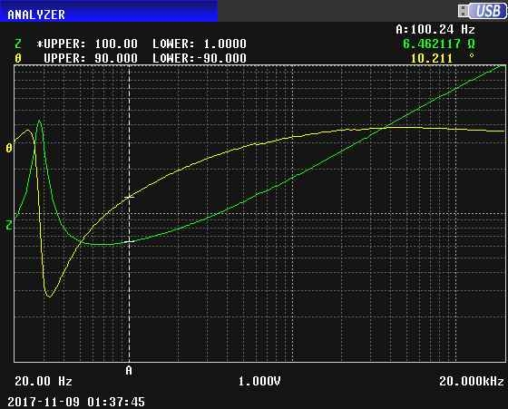
Can I do this to measure the impedance of a speaker ? :thinker:

Audio1----------A---------variable resistor---------B----------speaker----------C-----------audio2

Connecting a speaker and a non-inductive variable resistor in series;
Feed 1KHz sinusoidal signal to terminals 1 and 2,
Measuring the voltages AB and BC until they are the same by varying the resistor,

The speaker impedance will be the set resistor value, for the fed frequency.

Repeating at other frequencies to yield a plot.

¿?
 

Hi
Your method will work out but not looking bright.
Better to put fixed resistor instead of variable in your test method and measure voltage across fixed resistor
I = V(resistor)/DCR(resistor)
Then measure voltage across speaker
Impedance (Z) = V(speaker)/I
Repeat the above test for different frequency and plot the impedance
This will give you perfect impedance of a speaker
:thumbsup:
 

Hi,

I agree with the fixed resistor.
It shoukd be no wire wound. The resistor value should be close to the expected speaker value.
If you expect 4...16 Ohms, then use a 10Ohms resistor. Not a 10k resistor for example.
Don't use loud levels, because the impedance will move as soon as the speaker will distort the audio signal.

The speaker impedance is: Z = R x U_spk / U_R

Klaus
 

Measuring AB and BC voltage (either with fixed or variable impedance) gives only impedance magnitude. You may be interested to acquire the complex impedance. This can be done by measuring additionally voltage AC and some calculations or a vector voltmeter.
 

Hi
Your method will work out but not looking bright.
Better to put fixed resistor instead of variable in your test method and measure voltage across fixed resistor
I = V(resistor)/DCR(resistor)
Then measure voltage across speaker
Impedance (Z) = V(speaker)/I
Repeat the above test for different frequency and plot the impedance
This will give you perfect impedance of a speaker
:thumbsup:

What do you mean, "not looking bright"?

Why is it better to use a fixed resistor?

- - - Updated - - -

Here's a sweep of an 8 ohm 12" woofer done on an impedance analyzer. The sweep is from 20 Hz to 20000 Hz with the impedance magnitude in green and the phase in yellow. The impedance scale is logarithmic with 1 ohm at the bottom and 100 ohms at the top. The phase scale is linear with 90 degrees at the top and -90 degrees at the bottom. Zero degrees is at the middle, so when the phase is near the middle this means that the impedance is mostly resistive. A resonance can be seen near 28 Hz:

3722080000_1510262736.jpg


Here's a sweep zoomed in on the lower frequencies. At 10 Hz, the impedance is 6.15 ohms, and at the resonance frequency of 28.35 Hz the impedance is 44.68 ohms. Also note that from resonance to about 75 Hz the impedance is capacitive (the yellow curve is below the middle):

3285270500_1510262968.jpg
 
Last edited:
  • Like
Reactions: FvM

    FvM

    Points: 2
    Helpful Answer Positive Rating
Thank you for your responses, gentlemen.

Trying wording in more 'elegant' forms :

- The resistor magnitude inserted in series to the speaker equals its 1KHz impedance when insertion brings the speaker voltage to half.

- The inserted series resistance that halves the speaker voltage is its impedance value at 1 KHz.

- Measure the voltage across the speaker at 1 KHz. Insert a series resistor that halves the voltage. R = Z

And works not only for audio, but other circuits at their frequency of interest. Can be done to measure source impedance and load impedance of varied circuits ?
 

- The resistor magnitude inserted in series to the speaker equals its 1KHz impedance when insertion brings the speaker voltage to half.

- The inserted series resistance that halves the speaker voltage is its impedance value at 1 KHz.

- Measure the voltage across the speaker at 1 KHz. Insert a series resistor that halves the voltage. R = Z
All your statements are wrong, I am afraid. Methods that will work are discussed in post #2,3 and 4.

The reason is simple: the sum of the magnitude of 2 elements connected in series is NOT the magnitude of the equivalent element unless both elements are purely resistive.

Here's a sweep of an 8 ohm 12" woofer
Just curious, why is it called an "8 ohm" woofer if based on its impedance plot, seems like it has nothing to do with 8 ohms ?
 
Last edited:

At 10 Hz, the impedance is 6.15 ohms, and at the resonance frequency of 28.35 Hz the impedance is 44.68 ohms

Some more points of interest:

The green line (in the lower figure) is the absorption graph. The white line (phase) is the dispersion graph. X-axis is the excitation frequency. This is a characteristic of ALL resonance phenomena.

Note the change of phase near the absorption peak; it is zero at the peak. It again becomes zero near around 70Hz? What does that mean?

The impedance at the peak of the absorption curve is a measure of Q - in this case of the speaker, it is about damping. How they are related?

The speaker is critically damped - it appears to be a good one.

Lots of info hidden in the curves- young engineers will be certainly excited.
 

Some more points of interest:

The green line (in the lower figure) is the absorption graph. The white line (phase) is the dispersion graph. X-axis is the excitation frequency. This is a characteristic of ALL resonance phenomena.

Other disciplines may use these terms, but in the audio business they are not used. The terms used in the audio business are "impedance magnitude (or less precisely, just impedance)", and phase.

Note the change of phase near the absorption peak; it is zero at the peak. It again becomes zero near around 70Hz? What does that mean?

The phase is zero when the impedance magnitude is at a local maximum or minimum. This is because Foster's Reactance Theorem applies to this situation: https://en.wikipedia.org/wiki/Foster's_reactance_theorem

The impedance at the peak of the absorption curve is a measure of Q - in this case of the speaker, it is about damping. How they are related?

The speaker is critically damped - it appears to be a good one.

Lots of info hidden in the curves- young engineers will be certainly excited.

These curves are for the speaker in free air suspended from the ceiling, away from other objects. It is underdamped in this condition. A proper enclosure plus amplifier output impedance and crossover filter should properly damp it.

- - - Updated - - -

Just curious, why is it called an "8 ohm" woofer if based on its impedance plot, seems like it has nothing to do with 8 ohms ?

It is always the case that dynamic loudspeaker motors (speakers, in other words) have a DC resistance, or very low frequency (well below resonance) impedance that is about 75% of their "rated" impedance.

I guess that if one takes some sort of average of the impedance over the intended operating frequency range it would be about the rated impedance.

- - - Updated - - -

Thank you for your responses, gentlemen.

Trying wording in more 'elegant' forms :

- The resistor magnitude inserted in series to the speaker equals its 1KHz impedance when insertion brings the speaker voltage to half.

- The inserted series resistance that halves the speaker voltage is its impedance value at 1 KHz.

- Measure the voltage across the speaker at 1 KHz. Insert a series resistor that halves the voltage. R = Z

And works not only for audio, but other circuits at their frequency of interest. Can be done to measure source impedance and load impedance of varied circuits ?

As CataM points out, these methods don't work unless the impedance of the speaker is purely resistive. The method you described in post #1 will work because you are measuring the voltage across the resistor and the speaker separately, and varying the resistor until they are equal. When this happens, the voltage across the speaker will not be half the applied voltage because the speaker impedance is not purely resistive over most of the audio band. The speaker's impedance is only purely resistive at two frequencies--look at the yellow curve in the sweeps. Where the yellow curve crosses the middle of the plot is where the phase is zero and the impedance is purely resistive.
 

All your statements are wrong, I am afraid. Methods that will work are discussed in post #2,3 and 4.

Thanks. Without specialized plotting equipment to discern phasing; I was simply trying to find the impedance magnitude of unlabeled chinese speakers famous for their poorly specified ratings and published data (when there is any).

They are called '8 Ohms' impedance because that is a near figure to the frequency adopted as reference for audio. The impedance is strictly tied to the frequency of measurement. Otherwise, every speaker would have to be labeled with the entire response plot, which is too much for marketing and consumers.
There is an historical factor too, the output transformer impedances that were to match in the early audio days now carried for a century.

For a 'woofer' or 'subwoofer' ; the adopted standard reference may not be 1KHz, but whatever the manufacturer decides, changing expectatives as usually nobody knows what the manufacturer reference is. For a 'woofer' that is designed to never reproduce 1 KHz, makes no sense to specify its reference at such frequency.

Same with a television tuner... 75 Ohms input impedance is not real. The 'F' connector is such, but spanning 50 MHz to 800MHz, the 75 Ohm cannot be sustained along the spectrum. But still called 75 Ohm. Legacy. :sad:
 

For a rough impedance estimation, it's sufficient to measure the DC resistance, as discussed in post #9.
 

Status
Not open for further replies.

Part and Inventory Search

Welcome to EDABoard.com

Sponsor

Back
Top