Continue to Site

Welcome to EDAboard.com

Welcome to our site! EDAboard.com is an international Electronics Discussion Forum focused on EDA software, circuits, schematics, books, theory, papers, asic, pld, 8051, DSP, Network, RF, Analog Design, PCB, Service Manuals... and a whole lot more! To participate you need to register. Registration is free. Click here to register now.

[Moved]: Telescopic opamp psrr strange output

Status
Not open for further replies.

MahmoudHassan

Full Member level 6
Joined
Oct 4, 2010
Messages
349
Helped
44
Reputation
90
Reaction score
40
Trophy points
1,328
Activity points
3,913
Hello
Dear All
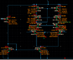
I designed a telescopic Opamp to get high gain. The circuit is working good and the gain as shown is 65dB and all transistors are working in Saturation.
The main problem is in PSRR test:
What I did is adding 1V AC signal with VDD and using ADE in virtuoso
Results> Direct PLOT> AC DB20
The output is really strange as the PSRR is positive !

IS this test methodology is correct for PSRR?


Attached circuit, gain and PSRR figures
Selection_458.pngSelection_457.pngSelection_456.pngSelection_455.png
 

Re: Telescopic opamp psrr strange output

I don't think it's strange. You are measuring gain from supply and your supply gain is I guess 1.05 or something but your signal gain should be much larger than this, maybe 80dB or so. You'd usually care about signal gain/supply gain because in a loop that's what matters. If you want real suppression of supply gain you should use an active loop with a fully differential opamp, then you'd get negative supply gain because there would be a loop controlling it.

You can run an xf simulation to compare signal gain to supply gain simultaneously.

Is what I did is the right way to measure for PSRR ?
What XF Simulation and how can I do it ?
 

Re: Telescopic opamp psrr strange output

I don't want to debug your simulation setup, but it looks like what you are doing is the right way to measure the gain from supply. In most cases however PSRR is defined as signal gain / gain from the supply input, so if you have 80 dB gain at DC and 1 dB gain from supply at DC you actually have 79 dB PSRR according to this definition. Because your signal gain is 79 dB more than your gain from supply. As you use the opamp in a loop this will change though.

In the end the definition of PSRR is kind of up to you, so think about your requirements and do the most relevant simulation.

In xf simulation you can put two different AC signals, so you wouldn't have to run two ac simulations (one for signal gain and one for supply gain).
 
Re: Telescopic opamp psrr strange output

I don't see any sign that you are doing this analysis in
closed loop configuration (which is the only way PSRR
matters).

Setting it up as a unity gain follower would give you a
reasonable answer / expected behavior.
 
Re: Telescopic opamp psrr strange output

I don't want to debug your simulation setup, but it looks like what you are doing is the right way to measure the gain from supply. In most cases however PSRR is defined as signal gain / gain from the supply input, so if you have 80 dB gain at DC and 1 dB gain from supply at DC you actually have 79 dB PSRR according to this definition. Because your signal gain is 79 dB more than your gain from supply. As you use the opamp in a loop this will change though.

In the end the definition of PSRR is kind of up to you, so think about your requirements and do the most relevant simulation.

In xf simulation you can put two different AC signals, so you wouldn't have to run two ac simulations (one for signal gain and one for supply gain).

Do you have any tutorials that can teach me how to do this XF Simulation ?

- - - Updated - - -

I don't see any sign that you are doing this analysis in
closed loop configuration (which is the only way PSRR
matters).

Setting it up as a unity gain follower would give you a
reasonable answer / expected behavior.

Thanks a lot it worked and gave me reasonable curve
Selection_459.png

- - - Updated - - -

IF I designed another opamp folded cascode one and it gave me good gain as photo attached
but PSRR test (while setting it up as a unity gain follower) provided bad PSRR at high frequencies what may cause this problem ?

Selection_461.pngSelection_460.png
 

Re: Telescopic opamp psrr strange output

The more complex the op amp, the more places there are
for supply activity to enter and be amplified. Cascodes
mean common rails, often weakly driven and unfiltered,
and possibly coupled to the wrong rail (Cgd, Cbs). You
want NMOS/NPN bias rails not to move relative to Vss/Vee
and PMOS/PNP bias rails not to move relative to Vdd/Vcc.
But the NMOS drain (say) that feeds the PMOS current
mirror racks, jerks away from Vdd when Vdd jumps and
puts a current impulse on top of DC bias, etc. You may
need to add some AC guards that minimize how much
the critical drains can be "tugged" (without messing up
headroom and so on). And if N and P racks diverge, that
is all kinds of bad.

Probing around for AC activity can show you where
sensitivities are. Tedious, but should show you where
to work.
 

Status
Not open for further replies.

Similar threads

Part and Inventory Search

Welcome to EDABoard.com

Sponsor

Back
Top