Continue to Site

Welcome to EDAboard.com

Welcome to our site! EDAboard.com is an international Electronics Discussion Forum focused on EDA software, circuits, schematics, books, theory, papers, asic, pld, 8051, DSP, Network, RF, Analog Design, PCB, Service Manuals... and a whole lot more! To participate you need to register. Registration is free. Click here to register now.

Transformerless Power Supply (230 volt to +12v/500ma)

Status
Not open for further replies.

Bjtpower

Full Member level 5
Joined
Dec 24, 2015
Messages
297
Helped
2
Reputation
4
Reaction score
2
Trophy points
1,298
Activity points
3,893
Deal Friends.

I am having an task of Transformerless power supply which can be from 230v ac Mains supply.

I know the Reactance of Capacitor=Xc=V/I
Where V=230*1.41=320V
i=500mA=0.5A
SO,Xc=320/0.5=640 ohm

Now Xc=1/(2*PI*F*C)
Rearranging will give me C=1/(2*3.14*50*640)=1/208998=4.7uF
therefore 4.7uF/400VAC Polyfilm cap i can use..

Is my calculations are right..??

Again, what is value for resistor which can resist 500 mA of current.

i have attached reference circuit which i got from the net.

and i want to do the modifications in the same.
Help

cp supply.gif

Marx
 

Hi,

Again, what is value for resistor which can resist 500 mA of current.
I is known, so it is a question of P and R..

P = I^2 * R --> P = 0.25 A^2 * R

Klaus

Added:
Is my calculations are right..??
No.

Your zener is 5.1V. --> You don´t get 12V output.
You calculated as there is the full 230V across the capacitor, but there is the zener, and the resistor....

Without load, the 12V zener dissipates at least 12V x 0.5A = 6W... it will become pretty hot.

--> use a simulation tool.
 

Hi KlaussSt
That is reference Circuit which i posted.
so zener will be off +12V.

Again calculation for Resistor value i didnt understand..??
The voltage across resistor and Cap (series) will be 324-12=312V.

I am not getting the resistor and cap combinations?

Are my capacitor value is wrong..??
 

Hi,

Again calculation for Resistor value i didnt understand..??

Power dissipation depend on resistor value..
or: resistor value depend on max. power dissipation.

You should decide one of the values than you can claculate the other value.

****
Why do you calaculate XC with the PEAK voltage? Usually it is calculated with the RMS voltage.
Voltage across capacitor is: total_voltage - voltage_across_diode - voltage_across_R

****

Again: use a simulation tool.
It seems you are not experienced to see what happens by the view of a schematic. So with a simulation tool you can see what happens when....
And see each current and voltage without the risk of smoke and fire....

Klaus
 

T Less.png

Try 1 uF capacitor and series resistor circuit, Capacitor should rated 270VAC X2 type
 

Hi,

@smijesh:

the diode is at the wrong place. --> it won´t work.

Klaus
 
page 4 of ST application note : http://www.bdtic.com/download/ST/AN1476.pdf
you need some 22µF/400V X2 capacitor to do what you want.
better use a small smps or a small transformer power supply, the capacitor you need is bigger than the transformer ...
 
  • Like
Reactions: FvM

    FvM

    Points: 2
    Helpful Answer Positive Rating
When you want several hundred mA, you need a full diode bridge.

The capacitor needs special consideration, or else it won't survive. Think of a large startup surge of current going through it. Think of one Ampere going back and forth through it in normal running. A safety resistor is a good idea. Consider how much it will heat up.

Although the capacitive drop supply looks good on paper, I've seen at least one expert report that 100mA is the maximum you should expect in practice.

I agree with previous post, a transformer is safer and easier to work with.
 

P = I^2 * R --> P = 0.25 A^2 * R

Just a remark, that total dissipated power on R should account the phasorial "real" part of the current, as well the expected load consumption. Depending on the C value selected, it could be not that negligible.
 

Guys..
I need calculations for how to calculate it..

i have given all the Terms..??

Where i am getting wrong..??
 

I'm cheating by running a simulation (with full-wave diode bridge). The dropping capacitor has 230VAC on it. (No need to calculate peak voltage 330V.) It needs 700 mA AC going through it, to give you 12V 500mA.

To pass 700mA, the capacitor should have a reactive impedance of 230 / 0.7.

The formula:
XC = 1 / (2 Pi f C)
is one building block of the calculation. If you end with that, however, it's an oversimplification. You also need to draw the parallelogram angles. It might have to do with high power factor error in this circuit.

Anyway my simulation shows 10 uF as a suitable value. That's with diode drops, zener drops, etc.
 

Guys..
I need calculations for how to calculate it..

i have given all the Terms..??

Where i am getting wrong..??
Faults in the post #1 calculation are:
- there's no substantiation to put in factor 1.41 in the calculation. The available DC output current has to be calculated based on average rectified value, about 0.9 * Irms
- secondly you are using a half-wave rectifier, so you get only half of rectified input current

Means the given circuit would need about 1.1 A input current for 0.5 A DC output. Results in > 15 µF (e.g. 22 µF) series capacitor.

You need to consider the series resistor voltage drop and rating, as already mentioned. Also the Z diode rating. All in all the circuit is badly suited for 0.5 A DC current.
 
the diode is at the wrong place. --> it won´t work.

Can you explain why the circuit in #5 not working ?????????
 

Hi,

A diode in series with a capacitor...without branches...

The capacitor can carry AC currents only
The diode can carry DC currents only

I'm repeating: use a simulation tool

Klaus
 

the diode is at the wrong place. --> it won´t work.

Can you explain why the circuit in #5 not working ?????????
How do you expect AC current to go through the capacitor with the diode in series ?????????
The capacitor will charge up to the peak negative AC voltage and then stop conducting.
 

What type of capacitor will used here..

I have many Cpacpcitors like X2/Y2 and other.. i want to use the exact capacitors.

Or any part no associated with this.
 

i want to use the exact capacitors
Means what? Capacitor values have been previously calculated in this thread.

I have many Capacitors like X2/Y2
Do you see any Y2 type with capacitance in the 10 µF range? No. So why are you mentioning Y2?
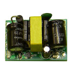
You need AC capacitors rated for 250 VAC or more. X2 capacitors aren't bad, but other AC capacitors can be used. The capacitor will be most likely larger than an off-the-shelf 6W SMPS module.

ACDC.jpg
 

What will be name Type of Capacitors..
mkp..?? polyproplene..??

I dont have knowledge on ac capacitors and its usage.

Thanks
 

What will be name Type of Capacitors..
mkp..?? polyproplene..??

MKP is a German acronym for metallized polypropylene film capacitors. Many AC capacitors use polypropylene film dielectric, but not all polypropylene capacitors are rated for AC. You'll look at manufacturer and distributors selection guides.
 

Status
Not open for further replies.

Part and Inventory Search

Welcome to EDABoard.com

Sponsor

Back
Top