Continue to Site

Welcome to EDAboard.com

Welcome to our site! EDAboard.com is an international Electronics Discussion Forum focused on EDA software, circuits, schematics, books, theory, papers, asic, pld, 8051, DSP, Network, RF, Analog Design, PCB, Service Manuals... and a whole lot more! To participate you need to register. Registration is free. Click here to register now.

Colpitts for wireless power

Status
Not open for further replies.

Heyviator

Newbie level 2
Joined
Apr 25, 2016
Messages
2
Helped
0
Reputation
0
Reaction score
0
Trophy points
1
Activity points
28
Hello,

I am trying to design a Colpitts oscillator with the end result of lighting up a couple 1w LEDs over the air.

I have looked up basic design rules on voltage divider based colpitts. I have trouble simulating these circuits in LTspice and Everycircuit it really seems to me like the results vary based on the timescale I choose.

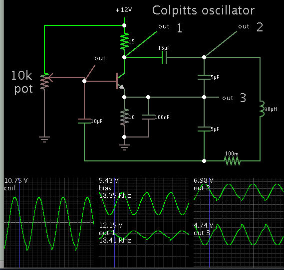
I made the attached in LTspice and it showed the circuit oscillating, but when I built it I got nothing but a low DC signal on my oscilloscope from the emitter to ground.

If someone could point out where I am going wrong that would be great. What may really be the most helpful is if anyone could recommend a place to start learning about the design of these circuits. I have learned a bit about biasing a transistor but that is about all I've got.

I have an excel sheet for my calculations if that would help you help me.

Thanks for your time!
 

Attachments

  • 20160422_201542.jpg
    20160422_201542.jpg
    528.2 KB · Views: 97

With your values the transistor has a gain of .2 (Rc/Re), try changing the 2 ohms to 200. There should be no Ce. Cc should be an RF type, try 1000pF. Look with Google at other peoples Colpitt oscillators to get an idea of component values. No point in trying to re-invent the wheel.
Frank
 
I suppose your aim to push as much Amperes through the inductor as possible? So it sends out the strongest magnetic flux field?

Tips:

* Bias setting is tricky, to find a good operating point for the transistor. Therefore adjust with a potentiometer. (A high ohm value might work better than a low ohm value.)

* It usually helps to make the inductor Henry value several times the capacitor value.

* Sometimes a low supply voltage makes oscillations start more easily.

* Adjust collector and emitter resistors, since it might make oscillations start more easily.

Because I like to run simulations, I applied the above tips to your schematic.


The simulation indicates 3A going through the inductor. I gave it a reasonably realistic ohmic resistance of 1/10 ohm.
 
I am not an expert on this but I think 29.6 kHz is a low frequency to transmit power over the air (also depends on the coupling coefficient). I think a more appropriate oscillator to transmit power has oscillating frequency on the mega hertz range.

Current as Brad says is also important to achieve a big flux, but you will still have to keep an eye on the loses...
 

This recent thread was about wireless power transmission. The OP achieved success eventually. He generated waveforms which went to a coil, although the waveforms were not created by a Colpitts.

https://www.edaboard.com/threads/348712/
 
I am not an expert on this but I think 29.6 kHz is a low frequency to transmit power over the air (also depends on the coupling coefficient). I think a more appropriate oscillator to transmit power has oscillating frequency on the mega hertz range.

Current as Brad says is also important to achieve a big flux, but you will still have to keep an eye on the loses...

Why does a higher frequency allow for better coupling? Is there an equation or other reference that could explain this.

Frank - Can I use an electrolytic for the decoupling capacitor off of the collector? The value in Brad's circuit is high for a ceramic.

To BradtheRad - What is the source for your tips? Is there something I can look into that would help me understand why these conditions need to be met?

Thanks for your help guys.
 

Why does a higher frequency allow for better coupling? Is there an equation or other reference that could explain this.

Transmit over the air cause coupling factor to decrease, so , you should increase the quality of the coils for a better transmission i.e. increase Q factor which is achieved increasing frequency and L. It is true that increasing frequency is more used to increase distance between coils, but if your coils are stationary and close enough, then ok.

If your frequency is low, your coils should be very close to each other.

"Quoted from Analysis and optimization of Magnetically Coupled resonators for Wireless Power Transfer - IEEE"

Because the power transferred is a function
of frequency, the operating frequency should be several
megahertz in order to obtain maximum power transferred efficiency
[5]. In addition, it is essential to reduce the copper loss
in the coils in order to decrease the power dissipation and to
increase the power transferred efficiency. At high frequencies,
the resistances of the coils are greatly increased because of skin
effect and proximity effect. To mitigate against these effects,
multi-strand Litz wires are used [6].


However, first try with your designed frequency and measure the results.

You should prepare the design for the worst case... assuming low coupling coefficient because over the air the flux gets very distorted, you do not have a magnetic core to concentrate the flux in your case like transformers do...
 
Last edited by a moderator:
Status
Not open for further replies.

Similar threads

Part and Inventory Search

Welcome to EDABoard.com

Sponsor

Back
Top