Continue to Site

Welcome to EDAboard.com

Welcome to our site! EDAboard.com is an international Electronics Discussion Forum focused on EDA software, circuits, schematics, books, theory, papers, asic, pld, 8051, DSP, Network, RF, Analog Design, PCB, Service Manuals... and a whole lot more! To participate you need to register. Registration is free. Click here to register now.

[SOLVED] Multi Pt100 for Pic18 with unstable power

Status
Not open for further replies.
It is unwise to maintain unnecessary headroom. If you are sure that the max temp will not exceed 250, then use a correct resistor so that you can use the full range.You may have other sources and it pays to account for the unexpected.
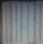
 

The next step - formula to transform ADC numbers to temperature.
I build a line on 2 points 0C and 300C.
Formula looks like TempC=0.715*LSB-378 or something.
20160301_164320.jpg
Real transformation is non linear and I got 11.2C mistake at 150C. It will work but I dont like this fact.
Tomorrow I create formula with 3 different lines for ranges 0-100, 100-200, 200-300 and calculate new mistakes.
I think it would be better than to add coefficients with squares or roots.
Now I can say that for 0, 100, 300 mistake will be close to 0, the biggest mistakes will be at 50 150 250. It sure will be much less than 11, I expect 2-3 degrees.
 
Last edited:

There are quadratic and cubic approximations for R(T) as well as T(R). For you case, because the range is small, a quadratic approximation will be good enough (give 1C). Or, you can take the same table and fit a quadratic or a cubic equation (curve fitting).
 
I have done a project of PT100 and I am getting these values

For 0 degree C I am getting 0.004 degree C
For 100 degree C I am getting 101.65 degree C
For 200 degree C I am getting 200.63 degree C
For 250 degree C I am getting 250.29 degree C

My Company doesn't allow me to post the code but I can help you with the calculation. I am using the RTD PT100 Temperature Calculation formula.

I am attaching the Proteus 8.3 SP2 format Simulation file. You test it. It is for full range i.e., -200 to 850 degree C.

I can't post the code but I can help you with the calculations.

See the attached image. it shows PIC18F46K22 measuring 250 degree C using PT100.

The attached document (PDF) shows these PT100 resistances for 250 degree C.

250.00 194.10 194.46 194.82 195.18 195.55 195.91 196.27 196.63 196.99 197.35 250.00

I am getting 194.20

- - - Updated - - -

Check the temperature and resistances from the attached PDF.
 

Attachments

  • PT100 Temperature Measurement.rar
    29.1 KB · Views: 91
  • PT100.png
    PT100.png
    37.7 KB · Views: 129
  • TD_TV_PT1A.pdf
    61.7 KB · Views: 97
Last edited:
I am attaching the Proteus 8.3 SP2 format Simulation file. You test it. It is for full range i.e., -200 to 850 degree C.

If you do a curve fitting with the required range, i.e., 0 to 400C, you will also get a better fit.
 
No, not really. You fit a curve T=a+b*R+c*R^2+d*R^3 using the data you have. Once you get the values of a,b,c and d put them in a function and get the value of T from R. You need to determine a,b,c and d only once. The curve fitting can be done once on a PC just to get the parameters.
 
Excel can be used for getting the a, b, c and d values ? If not, what software can be used to get the values and how ?
 

Open excel worksheet

put temp in one col
put resistance in another col
Select both
click insert
select scatter plot
select all points
select trend line
select polynomial order 2 or order 3
check box display equation on plot
you see the result.
 
formula y=ax^2+bx+c gives 0.45C mistake, which is enough.
 

1. Don't use MC34063 to power up the microcontroller. If you want, increase the output voltage of the switching regulator to 6V or above & connect a 5V LDO. Now connect the output of the LDO to powerup the microcontroller.
2. 10bit ADC is not enough. You have to use 12 bit ADC at the least for acheive below 1°C accuracy.
3. Use constant current source of 1mA. 20mA current source will introduce RTD self heating problem & again you will get the erratic reading.
4. If RTD wire length is more then 3 meters, you have to include wire length componsation circuit to reach the accuracy.
5. You must have to include a differential amplifier(with very low input offset voltage) to get the output span.

I'm using a RTD circuit as you can see in attachment which is 3 wire. If you are using 4 wire RTD, then you may have to make changes in circuit to get even better accuracy.

Udhay
 

Attachments

  • RTD.JPG
    RTD.JPG
    95.2 KB · Views: 106
Excel gave this equation for Order 3 Polynomial. How to use it now ?

y = 2E - 08x^3 - 7E-05x^2 + 0.3918x + 100.04

x is RTD PT100 resistance ?

E = e ?
 
Last edited:

Excel gave this equation for Order 3 Polynomial. How to use it now ?

y = 2E - 08x^3 - 7E-05x^2 + 0.3918x + 100.04

x is RTD PT100 resistance ?

E = e ?

The x is resistance and y is temperature (first col is x and the second col is y)- I hope.
2E-08 simply means 2*10^(-8); 7E-05 means 7*10^(-7).

If you want resistance as a function of temp, just interchange the x and y columns in the spreadsheet.
 

The equation is giving wrong results. It should give 0 deg C for x = 100.

Got it. now it is working but my earlier calculation was giving more precise results. Now it gives 1.2 deg C defference for 300 deg C.
 
Last edited:

udhay_cit, your advice about power supply is very useful.
About 10/12 bit ADC.
I don't need 1°C accuracy, I only need 1°C resolution for temperature representation.
The unit just need to keep stable preset value. Noone cares about absolut value.
Operator checks the heating result and up/down preset value. That's it.
It's done.
I took 3 points 0 150 300 and corresponding LSB by Proteus for my scheme.
I found A B C in group:
0=A*LSB0*LSB0+ B*LSB0+C
150=A*LSB150*LSB150+B*LSB150+C
300=A*LSB300*LSB300+B*LSB300+C
(thank c_mitra)

and I got a formula TempC=A*LSB*LSB+B*LSB+C (which I complicated for 2 parameters to adjust slope and offset)
As I told it has 0.45C mistake with Proteus simulation

I've already tried the measuring unit today, it works quit plausible. (The range was 0-180 and real mistake was 2C. Mistake I mean the differense between real and calculated by PIC temperature. It doesn't matter for keeping stable heating level. It does matter power/noise/filtering.)
Though I'm going to create better software noise filter.

Your temperature unit looks good but it is overloaded by components.
I build (copied actually) very simple unit and it will carry out the task - keeping heater at preset temperature.
Although I still have to do next step - create some PID regulation algorithm - for minimazing temperature span because of heater inertia.
 
Last edited:

Hi,

your advice about power supply is very useful.
As said before...the now used combination is the worst combination regarding accuracy.
Either use a voltage divider as reference, or a stable supply for the pt100.

Klaus
 
I tend to place power sources on another board to play with them independently.
The mainboard will have free lines to connect Vref+/- and special line to power up sets of Pt100.
The general idea Pt100+R1 will stay.
The main power supply might be changed.
The special power supply only for Pt100 might be added.
 

Status
Not open for further replies.

Similar threads

Part and Inventory Search

Welcome to EDABoard.com

Sponsor

Back
Top