Continue to Site

Welcome to EDAboard.com

Welcome to our site! EDAboard.com is an international Electronics Discussion Forum focused on EDA software, circuits, schematics, books, theory, papers, asic, pld, 8051, DSP, Network, RF, Analog Design, PCB, Service Manuals... and a whole lot more! To participate you need to register. Registration is free. Click here to register now.

Sine wave inverter voltage clipping (transformer saturation?)

Status
Not open for further replies.

kathmandu

Full Member level 5
Joined
Dec 7, 2015
Messages
298
Helped
7
Reputation
14
Reaction score
7
Trophy points
18
Activity points
3,146
Hello,

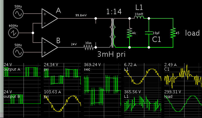
I'm in the process of building a sine wave inverter (Mosfet full-bridge and a low freq transformer).

Anyway, I don't manage to tune up the output filter (a series inductor in the transformer primary circuit and a capacitor across transformer secondary).

I have tried different inductor cores (E shape ferrite, ferromagnetic toroid) but the output voltage isn't perfect (there are some perturbations around the middle point of every half wave - between the zero crossing and peak voltage).

This is happening at no load or with a small resistive load (60W bulb lamp).When I connect an AC fan (150W), the output is clipping harder (the wave form has almost a trapezoid shape) and the transformer starts humming.

The inverter is rated at + 1000 W (24 V DC link, 170 Amp Mosfets, 1000 W toroidal transformer). The clipping is not caused by low voltage DC-link (the battery bank is oversized too).

What could be the problem? What's the effect of a bigger/smaller filter inductance or capacitor? Thank you very much for your help.

I've attached some oscilloscope printscreens:


(1) - output voltage at no load (or small resistive load)


**broken link removed**


**broken link removed**


(2) - output voltage for an inductive load (400W corded power drill)


indload.jpg


indload-1.jpg


Does anyone have any clue about what's happening?
 

"there are some perturbations around the middle point of every half wave - between the zero crossing and peak voltage"
- Is it a "fuzz"? Are you using unipolar modulation?

"the wave form has almost a trapezoid shape)"
- is it symmetric, both top and bottom? Or only one side?
- Are you running close to 10% modulation index?

P.S. I just saw the waveforms

What is the waveform across your transformer primary? (use a differential probe)

How are you generating the gate drive patterns? micro?
 
Many thanks for your help!

Yes, I'm using an unipolar modulation. The PWM is generated using an MCU, indeed.

The wave forms look different now as I've changed the filtering inductor. They were trapezoid shaped at the time I've posted my first message. And yes, the wave forms were symmetrically distorted.

Unfortunately, I don't have a differential probe. I've checked the gate signal (without Mosfets connected) and they were very sharp (30ns rise/fall times) with no distortion at all.

Do you know what's the effect of a smaller/larger filtering inductance or capacitor? For now I'm using a toroidal choke inductor (100uH/50A) and 0.47uF (2.2uF) X1 capacitor.
 

Sorry your attachments expired (125678 & 125679). You'll need to try again. The 'Add an Image' button is reliable and straightforward.

To tell the truth, your waveforms look very much like waveforms I see on my oscilloscope, when I grab the probe lead. I'm pretty sure it's a replication of ambient 60 cycle hum, even though the probe isn't connected directly. It's a distorted sinewave, and I think it's caused by nearby appliances (example, refrigerator motors), either mine, or in the building, or the neighborhood. I suppose it would become a sinewave if all those appliances were turned off. Anyway the distortion doesn't cause serious problems, and if that's normal then maybe your own waveform is too.

- - - Updated - - -

(2) - output voltage for an inductive load (400W corded power drill)

Check for power factor errors. Does current waveform coincide with voltage waveform? Your inverter may be able to tolerate a misalignment, or it may not. You may need to add a capacitor for power factor correction.
 
I'm posting again the wave forms:


(1) - output voltage at no load (or small resistive load)


noload.jpg


noload-1.jpg


(2) - output voltage for an inductive load (400W corded power drill)


indload.jpg


indload-1.jpg


Check for power factor errors. Does current waveform coincide with voltage waveform? Your inverter may be able to tolerate a misalignment, or it may not. You may need to add a capacitor for power factor correction.

Do you mean the filtering capacitor (across the transformer secondary)? Or the DC-link ones?

- - - Updated - - -

I'm using a switching frequency of 12.5 kHz. Does it have any influence (being multiple of 50 Hz)? Do I have to choose another one, to avoid unwanted harmonics?

Could you tell me what influence may have a larger/smaller filter inductor/capacitor?
 

The PWM period is 80 uS and I have 125 pulses per half wave (125 x 80 uS = 10 ms). The rest of measurements (freq, Vrms, Vpp) are ok, too.
 

To tell the truth, your waveforms look very much like waveforms I see on my oscilloscope, when I grab the probe lead. I'm pretty sure it's a replication of ambient 60 cycle hum, even though the probe isn't connected directly. It's a distorted sinewave, and I think it's caused by nearby appliances (example, refrigerator motors), either mine, or in the building, or the neighborhood. I suppose it would become a sinewave if all those appliances were turned off. Anyway the distortion doesn't cause serious problems, and if that's normal then maybe your own waveform is too.

Reading your post again, I realised that the wires used to connect the inverter to the battery bank (for testing purpose) were actually pretty thin. I was relying on DC link capacitors but that running AC motor overwhelmed them.

Looking at the wave forms (inductive load), I should have seen that those voltage sags were occuring at the maximum power (voltage and current around the middle (top - bottom) of the sine wave).

I'm going to move the inverter near the batteries and I'll check the wave forms again.

Anyway, how should I tune that output filter? Is there a LC time constant I need to calculate? If the inductor is smaller (18uH) could I compensate with a bigger capacitor?

Thanks in advance for your kind support.
 

Try removing the transformer and using a simple RC lowpass filter instead as a load. Like 10Kohms and 100nF. That way we can see the filtered waveform without the transformer's impact.
 

Looking at the wave forms (inductive load), I should have seen that those voltage sags were occuring at the maximum power (voltage and current around the middle (top - bottom) of the sine wave).

Your motor is not necessarily pure inductive, nevertheless it might have a current-lag effect. This is the reason for a capacitor across AC motors, to correct power factor. I don't know how important it is in your case.

Anyway, how should I tune that output filter? Is there a LC time constant I need to calculate? If the inductor is smaller (18uH) could I compensate with a bigger capacitor?

Thanks in advance for your kind support.

Your carrier frequency is high enough to make it easier for you to filter out spikey behavior.

A smaller inductor makes its chief effect by increasing output voltage. (This is typical inductor effect.) A larger inductor reduces output voltage.

The capacitor value changes output voltage to an extent. It also is involved in power factor correction. A reasonable value is whatever results in the same Amperes going through it as through your load.

Their combined effect must be tailored to your load.
 
Try removing the transformer and using a simple RC lowpass filter instead as a load. Like 10Kohms and 100nF. That way we can see the filtered waveform without the transformer's impact.
That is exactly what I would do, but you beat me to it.

Fit a strong RC integrator to each bridge output half, and monitor the PWM output directly before any other filtering.

To me, the above waveforms look more like superimposed noise as already suggested by Brad.
 
A smaller inductor makes its chief effect by increasing output voltage. (This is typical inductor effect.) A larger inductor reduces output voltage.

I see the LC filter acting like a frequency dependent voltage divider. As the frequency goes higher, the inductor impedance is raising and the capacitor one decreases thus the high frequency voltage applied to the load is attenuated.

Anyway, the load itself has a rather complex and variable impedance. How to know if a given inductor is suitable or not in this particular case?

I'm asking you this because I have encountered the following situation: I bought an E ferrite core power inductor (13uH, 180 A, helical copper bar) to use it as a filter. I also have some sendust (iron powder) toroid inductors (47-68uH, 50 A).

I was convinced that the ferrite core inductor will best fit my application but the experimental results were disappointed. The filtering efffect was reduced (I've tried various output capacitors values) and the low frequency transformer kept humming quite loud.

On the other hand, the sendust toroids (I've tried different series/parallel combinations) seems to work better (but, like you said, their increased inductance steal the output voltage). How to choose a right inductor value?

The capacitor value changes output voltage to an extent. It also is involved in power factor correction. A reasonable value is whatever results in the same Amperes going through it as through your load.
I guess I'm not really get it straight: if the load current is 50 Amps, do I have to expect an identical current flowing through the capacitor?... thus the inverter have to supply 100 Amps? I'm missing something, for sure. Could you elaborate, please?

There have to be some (LC) time constant in relation to the output frequencies - the modulating one (50 Hz) and the sampling one (12.5kHz). Do I have to set the cut-off frequency of the low pass filter in between those two frequencies (like 500 Hz or something)?

- - - Updated - - -

To me, the above waveforms look more like superimposed noise as already suggested by Brad.

Don't you think that a superimposed/radiated noise were supposed to show up at the same voltage level, regardless of the load current? I'm so frustrated that I could not make some tests right now, but those voltage sags really looks like a drop in the DC link voltage (that is the region of maximum inductive load power).

Don't you think that a weak DC link should look like that?
 

If it was an LC output filtering problem, whatever residual high frequency ripple exists, would be all over the entire sine wave.
It would not create the odd notches and weird distortions that you are seeing.

Insufficient output filtering usually looks more like this:
ripple.jpg
 

I was talking about insufficient DC link capacity to sustain a higher load current.

At zero crossing and peak voltage, the power surged is zero (P = V x I, V= 0 or I = 0). At the middle region, the V x I is at maximum thus the current surged from the battery (DC link) will be maximum hence the voltage drop across those thin wires (6 m long, 2.5mm2 section) would be large.

The DC link capacitors could not sustain such a large current thus the input voltage of the inverter sags and that is mirrored to the output, too (the h-bridge could not sustain the increasing trend of the output voltage).

The insufficient output filtering looks like that, indeed.. but this is not the problem of those wave forms (they are clean, as you can see).
 

WHen you do not have a low source impedance like the grid, a poor load regulation is expected. Normally your source impedance should be 1% of your worst case load impedance for 1% distortion abd that would be assuming a perfect sine no load response.\

There is a direct relationship here between source/load impedance ratio , we call load regulation error.

There will be a complex impedance of commutation and harmonic back EMF etc for motors as well as complex source impedance commutation with time-varying ESR from RdsOn, magnetics and other components.
 

I bought an E ferrite core power inductor (13uH, 180 A, helical copper bar) to use it as a filter.

Then my simulation below is different from your topology, perhaps. My filter is LC second order butterworth, at the output. The transformer primary has a SPWM carrier of 900 Hz (in order to make waveforms observable).

I guess I'm not really get it straight: if the load current is 50 Amps, do I have to expect an identical current flowing through the capacitor?... thus the inverter have to supply 100 Amps? I'm missing something, for sure. Could you elaborate, please?

No, 50 A is all it needs to provide. The capacitor and inductor and load all have current going through them slightly out of phase with one another. Although the inductor could conceivably be all you need, I'm pretty sure the capacitor is also needed to correct power factor elsewhere in the circuit.


My simulation has a capacitor with too low a value, in order to illustrate insufficient power factor correction. The secondary influences the primary. See the scope traces in the primary? The Ampere waveform lags the voltage waveform. This is not an optimal way to operate an H-bridge. A larger capacitor will solve this by creating more leading effect in the Ampere waveform.

A larger capacitor will also increase output voltage. (My simulation has low output voltage).

I don't know if there is a formula for the way these components interact. I began to see it gets complicated after I played with simulations for long periods of time.

There have to be some (LC) time constant in relation to the output frequencies - the modulating one (50 Hz) and the sampling one (12.5kHz). Do I have to set the cut-off frequency of the low pass filter in between those two frequencies (like 500 Hz or something)?

A cutoff frequency of 80 or 90 Hz is good, from my simulation experiments. This is similar to an LC 2nd order filter which might drive a speaker crossover. There are online calculators for audio hifi systems, which will give you suitable LC values.
 
Need to reduce source impedance as was already said to avoid voltage drop. A higher switching frequency also may help to reduce these (with faster control loop).
Regarding output filter, your L is too small. Need to calculate an LC low pass filter with Fc at above 30% of output frequency (to avoid some resonance effects) and use a damping factor of 0.7. Check this link for calculation **broken link removed**
With 50mH and 100microF get 82Hz Fc.

Thank you very much for the link! From what I've read so far, the capacitor across the secondary winding will reflect its capacitance on the primary with a factor equal to the square of turns ratio. So if the turn ratio is 8 and I put a 10 uF capacitor across the secondary winding that's equivalent of a 10 x 64 = 640 uF (seen by the primary).

For an inductance of 13 uH and that "virtual" capacitor of 640 uF I got a cut-off frequency of 1744 Hz. Looks like I need a 4700 uF capacitor in secondary (300 000 uF primary equivalent) to get a Fc of 80 Hz though.

By the way, the transformer leakage inductance adds to the filtering inductor (being in series) hence I might have some extra uH from it.

I don't know if there is a formula for the way these components interact. I began to see it gets complicated after I played with simulations for long periods of time. A cutoff frequency of 80 or 90 Hz is good, from my simulation experiments.

Oustanding simulations! Could you try one more using my real parameters (f = 12.5 kHz, L = 13 uH, leakage inductance of 10 uH)? Thank you very much for your time.

I was afraid I was using a way too big capacitor (2.2 uF) across the secondary. The output voltage looked clean enough when I was using even smaller capacitors (1 uF) so I didn't try to experiment with larger capacitors. Now that I have some guiding lines, I'll try to add more capacitors though.
 

I think is better to remove cap from secondary and use LC filter; so, first is L and then a capacitor; with 50mH and 100microF can have a good filter; 50mH at your power level is hard to find / manufacture, is easier to increase capacitor and reduce L, to have same Fc and reduce cost of L (it's a trade-off, depending of what L may have/find). Transformer leakage don't have influence/filtering effect at 50Hz.
 

Status
Not open for further replies.

Similar threads

Part and Inventory Search

Welcome to EDABoard.com

Sponsor

Back
Top