Continue to Site

Welcome to EDAboard.com

Welcome to our site! EDAboard.com is an international Electronics Discussion Forum focused on EDA software, circuits, schematics, books, theory, papers, asic, pld, 8051, DSP, Network, RF, Analog Design, PCB, Service Manuals... and a whole lot more! To participate you need to register. Registration is free. Click here to register now.

LM2576 5.0 circuit output problem

Status
Not open for further replies.

SiddharthGajjar

Junior Member level 3
Joined
Jan 6, 2016
Messages
31
Helped
0
Reputation
0
Reaction score
0
Trophy points
6
Activity points
289
Hey There

i am using LM2596S 5.0 (fixed output)(SMD from National Instruments ) regulator to charge my power bank

i am using inductance of 100uH, input capacitance Cin 470uF/25V schottkey diode
SS34 3 Amp. output capacitance of 220uF/25V.

My Input voltage is 12VDC 2.0A adapter

i am about to get 5.0 V regulate but i am getting 1.22V only.

what is the reason and how can i get regulate 5.0 V
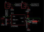
circuit diagram.png

this is my circuit diagram
 

no i am testing it on breadboard and i have ensure the connections they are connected well..
 

Hi,

please confirm the device you use is really the "5.0V" and not the "adj" version.

Klaus
 

edited.jpg

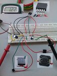
here is my circuit on breadboard which giving me 1.22Vdc output at pin 2

input cap. 470uF/25V
output cap 220uF/25V
ic lm2596 5.0 fixed
diode ss34
inductor tried with 220 & 100uH

output remains 1.22V DC

checked voltage at pin 4 Also but no change in voltage
 

Beadboard is OK for linear regulators, but this is a switching regulator & need very careful PCB design. You can't expect to get output from a switching regulator with this lengthy wires & connections. The inductor position & schottky diode positions are most important to make this circuit to working. Even with PCB, proper design is required to get the perfect output. You must avoid to use breadboard for the testing & for worst case you can use a through hole regulator & components which you should directly plugged into the breadboard without the lengthy wires involved.
I recommend you to test this circuit with a small size of general purpose veroboard. Note you have to take care of the inductor & schottky diode arragement and you can refer for this from datasheet PCB design sample & internet search also. Good luck.. Don't use this type of connection to test a switching regulator.

Udhay
 

Oh my friend!, what you show reminds me of my first ever smps.....something I like to forget.
Please repeat and do on Eagle free pcb layout and then here is pcb layout instruction for smps attached.
Sometimes you can get away with wireboard if you make the connectons really small...but smps really need pcb
 

Attachments

  • Basics of SMPS Layout _4.doc
    645.5 KB · Views: 176

That's the advantage of using a pcb software, you can check the schematic and see if its hooked up right. Sorry but the hookup of post#7 is not the way to go, it will cost you in the long run, its gambling with noise etc.
 

Have you used 100 uH 3A inductor ? If not then change the inductor.
 

I'm with Treez on this one. That breadboard will only give you grief.
Some individuals in this and other forums claim that they have built SMPS on breadboards successfully. To which I respond: some people can walk on a tightrope, most of us can't.

Additionally, one is depending on so many unknown variables.... For instance the leakage inductance and the contact resistance can easily trigger the ICs shutdown mechanisms.
 

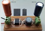
As per your suggestion i mount all the components on a Circuit board

took a new IC LMLM2596 5.0 fixed voltage with ss34 schottkey diode

1000uf/25V input and 1000/ 16V output capacitance.

inductor is 470 uH.

my input voltage is 12.0 Vdc 2 A but still this provides me 1.22V DC

i bought new ic although it gives me same response.
pls suggest me where is the mistake????

see image of my PCBcircuit mounted2.jpg

and uploading my schematic diagram also

brd.PNGscematic.PNG

- - - Updated - - -

yes i have tested it with PCB tody SEE Post #15
 

attached now is design document for buck with lm2596...what is you inductor value and peak curren trating, it should be about 33uh and 4a rated

- - - Updated - - -

looks to me like you have got wrong inductor in DR125
..YOURS SAYS "0.47", THIS CANNOT POSSIBLY BE 47Uh....so you have got wrong inductor. (sorry about capitals)

https://www.mouser.com/ds/2/87/Bus_Elx_DS_4315_DR_Series-248110.pdf
 

Attachments

  • buck 15w.zip
    1.9 KB · Views: 87

the inductor value is 47uH

are you sure that i will get 5.00 output when i replace the inductor with 33uh

so now i am feeding this circuit from 12dc 2A adapter, but we are going to use this circuit with solar panel to charge battery bank solar panel is giving output upto 22V and able to provide 1.5A current to my battery bank.

my battery bank will take 5.0 v and upto 2A for charging

so the calculations you gave with this configuration will work with that also??
 
Last edited:

your vout = 5v, and iout(max) = 2A?
yes that will work, with either 47uh or 33uh...as long as its RATED TO 4a
What is you vin?...I though it was 12v?

in photo, your inductor shows "0.47"...thatcannot possibly be 47uh.
And are you sure your diode is the right way round, and is of sufficient current rating?...and is schottky or ulta fast diode (if UF , then trr <50ns?)
 
perhaps you have the adj version which explains the 1.2 Vout if you connect the Vout direct to the f-back pin, you need to divide it down with resistors to get 5.0V out.. say, 120 ohms to gnd off the pin and 390 ohms from the pin to Vout...
 
in LM2596 5.0 fixed output regulator ic we read LM2596S -5.0 P+

so what means -5.0 P+

does it means Minus 5.0 ??????
 

Hi,

Datasheet tells you:
PDF.
Search for "Ordering information", "Packaging information"
Or search for "Device Marking"

Klaus
 

the fact that when you connect directly to that pin you get 1.22 V tells me it is an adj version - put the resistors in - it can't hurt, and if you get near 5V you know the part has been wrongly printed (it does happen..!)

EP
 

Status
Not open for further replies.

Similar threads

Part and Inventory Search

Welcome to EDABoard.com

Sponsor

Back
Top