Continue to Site

Welcome to EDAboard.com

Welcome to our site! EDAboard.com is an international Electronics Discussion Forum focused on EDA software, circuits, schematics, books, theory, papers, asic, pld, 8051, DSP, Network, RF, Analog Design, PCB, Service Manuals... and a whole lot more! To participate you need to register. Registration is free. Click here to register now.

Connecting Power Supplies in Series

Status
Not open for further replies.

Nun01

Newbie level 5
Joined
Jan 8, 2016
Messages
8
Helped
0
Reputation
0
Reaction score
0
Trophy points
1
Activity points
62
I want to connect two 24V, 6.3A power supplies in series to make a +/- 24V supply. The supplies are PMK150S-24E

**broken link removed**

The maximum current draw should be 5A.......what reverse polarity protection diodes would you spec (if any)? a part number would be great!
 
Last edited:
As a general rule switching power supplies have the - terminal referenced to earth ground. If you try to put two of these is series they will fight each other, as the minus terminal from the two supplies are both probably connected to case/earth ground.
 
  • Like
Reactions: Nun01

    Nun01

    Points: 2
    Helpful Answer Positive Rating
As a general rule switching power supplies have the - terminal referenced to earth ground. If you try to put two of these is series they will fight each other, as the minus terminal from the two supplies are both probably connected to case/earth ground.
I share your concern FlapJack.

But this particular supply has max voltage ratings for input to ground 2Kv, and output to ground of 500v. So presumably the output is fully floating with respect to the grounded metal case.
From that, it would follow that either the positive or negative side can be safely grounded.
You probably do not need polarity protection diodes, unless there is something really odd or special about the load you intend connecting.
 
I'm driving a galvanomter and it needs +/- 24V @ 5A. A dual bench supply is expensive, linear supplies are also expensive and heavy so I thought I'd see if a couple of switchers in series to create a bipolar +/-24V supply would work.
 

FYI I just found this on the manufacturer's website so it looks ok for series connection with the diode protection and a caveat about ripple. I'll call them up and ask about part recommendations for my application. I assume I'll need a diode with a forward current of around 6A ...see page 14

**broken link removed**
 

As Warpspeed says no diodes are needed presuming you connect them properly in series.
That doc you linked also says that one smps could affect the feedback loop of the other, but this wont happen as long as each output rail only draws current from its respective supply.
 

Yes thanks, my plan is to connect AC live, neutral and ground to one supply and then live and neutral to the second supply leaving it's ground to float. I'll make sure the supply cases are well insulated from eachother. Then I'll connect the output DC ground of the grounded supply to the +ve DC output of the other. Then the +24V of the galvo goes to +ve output of the first supply, the Galvo goes to the GND of the first supply ( and +ve of second supply) and the -24V of the galvo goes to the GND in the DC output if the second floating supply. I'll call the manufacturer to see if they recommend something like 10A diodes on the outputs.
 

As a general rule switching power supplies have the - terminal referenced to earth ground.
That's definitely not true for general purpose SMPS. The maximum output common mode voltage against PE is of course restricted, but surely no problem for 2 x 24V series connection. For the linked Astrodyne SMPS output isolation strength is e.g. 500 VAC.

Respectively both devices should have their PE connected, will be usually already achieved by mounting the metal case.
 

Respectively both devices should have their PE connected, will be usually already achieved by mounting the metal case.

Could you explain this a little more. I was planning on isolating the metal cases of the SMPS from each other and the connection to ground would be on the AC side of the first power supply (the +24V one).
 

As the datasheet clarifies, the SMPS has a isolated output, isolating the chassis ground is not appropriate, neither safety nor EMC related.
 

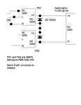
Here is what I'm thinking of doing. As the chassis are isolated do I need to worry about them touching or people touching them? The manufacturer does recommend some diodes and I'll give them a call on Monday to double check.

Bipolar supply diagram.png
 
Last edited:

Ground BOTH metal chassis to each other and mains earth.
Its a safety requirement and will have absolutely no effect on operation.
 
  • Like
Reactions: Nun01

    Nun01

    Points: 2
    Helpful Answer Positive Rating
Ground BOTH metal chassis to each other and mains earth.
Its a safety requirement and will have absolutely no effect on operation.

Should the AC GND on PS2 be connected to the mains earth as well?
 

It is highly recommended to add the anti-parallel diodes. 10A diodes are OK.
In case of exceeding the current limit the supply with the lower current limit can have its output reversed and get damaged.
 
Last edited:
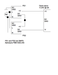
Thanks everyone. Here is the diode I propose to use 10A02

**broken link removed**

and the circuit now looks like this

Bipolar supply diagram 01.png
 

Status
Not open for further replies.

Similar threads

Part and Inventory Search

Welcome to EDABoard.com

Sponsor

Back
Top