Continue to Site

Welcome to EDAboard.com

Welcome to our site! EDAboard.com is an international Electronics Discussion Forum focused on EDA software, circuits, schematics, books, theory, papers, asic, pld, 8051, DSP, Network, RF, Analog Design, PCB, Service Manuals... and a whole lot more! To participate you need to register. Registration is free. Click here to register now.

Industrial Grade Robust Inverter Build Thread

Status
Not open for further replies.

chinuhark

Member level 5
Joined
Aug 16, 2014
Messages
88
Helped
1
Reputation
2
Reaction score
1
Trophy points
8
Activity points
1,051
To all Power Electronics experts out there,

I have a masters degree in power electronics, have done V/F successfully, made a hysteresis and PI based current controlled Inverters, done Thyristor control, mastered the dsPIC controller and so on. But a thing that has still eluded me and all my colleagues at my college is to make a ROBUST Inverter that does not blow up. After giving up on the idea of Power Circuit Design a few months back, I have decided to take it up as a challenge to make one.

This is what has inspired me:

https://tahmidmc.blogspot.in/2012/09/failure-is-pillar-of-success.html

I have done a lot of research online about IGBTs, gate drivers, blown up many IR2110s, studied PCB layout considerations, OC/SC protection, current sensors and so on but none of my designs has ever lasted for long when loaded by an actual motor. The waveforms were perfect, but smoke was always imminent. I don't know whether I was doing something very wrong or was just too damn unlucky. I don't know if this is a very simple task I am making a lot of fuss over.

My first question to you all is:
Does everyone blow up their first few inverters or is this something that should be quite straightforward?

I will be posting about my progress on this thread and request all of you to support this thread by providing your valuable opinions.

The basic plan right now is as follows:

- 2kW, 415V 3 Phase IGBT bridge
- Over Current and Short Circuit Protection
- DC Caps Precharge circuit
- Thermal Protection using thermistor

This brings me to question2:

Single IGBT or IGBT Module(without driver) or Intelligent Power Module(IPM)?

I am slightly reluctant to go the IPM route.
 

IR2110 is no good for 415Vac, making a good inverter is the preserve of experienced power electronics engineers.
 

I had used the IR2110 for 230V line to line inverter.
And if I don't try, how will I get experience.

Anyhow, single IGBT or module. Which is used for these power levels commercially?
 

if I don't try, how will I get experience
kinda painfully and slowly...

- - - Updated - - -

module gives better layout esp if rail caps are close by...
 

Hi,
Some words, hopefully of wisdom.

* Layout is everything. You need as little inductance between your DC link and DC snubber caps across the DC terminals of the module. This minimizes overshoot across the devices when they interrupting a large fault current.

* Proper IGBT gate drive is also very important.

* When I design an inverter, I go through a set of tests that I call pulse testing. This ranges from using an inductor to take the DC link volts, normally 600 in my cases. This should then take about 100us to hit headline rating of the device. The inductor goes across one device and you switch the other device into it. You then let the current decay a bit, then switch on for a short period extra. You can then watch the commutation of the opposite diode and hopefully pick something up from this. Repeat test the other way round with upper and lower device transposed.

* The later test is to purposely cause a shoot through, such that the protection works, and your gate drive solution remains stable. The shoot through scenario is your worst case event. Most IGBT's have a 10us short circuit rating. Personally I test this at room temperature, and at the device externally heated to the devices headline rating, 150°C for instance. IGBT's tend to work quicker when they are cold. The faster the device switching, the higher the voltage spike when interrupting a large shoot through current. If your gate drives goes unstable during a shoot through, then clearly all bets are off.

* Use a gate drive circuit that has internal soft turn off so that the device Vge is reduced and then turned off. I am using an ACPL-302J in my latest design. This vastly reduces the voltage overshoot at turn off at shoot through.

When you have done your pulse testing then you will have confidence that the inverter will stand up to most things. I have used this method upto 300kW and produced a very robust and reliable inverter. Until you have done all these tests then you don't *really* know.

Test gear required: Isolated DSO eg Tektronix , pulse generator, high voltage bench supply. Good to have if the test gear can be remotely triggered/driven over LAN, particularly for bigger inverters. Don't fancy being anywhere near it if it lets go. My last job at 20mF of caps at 700V on the DC link so do the sums.

Hope that helps.
 
Just a follow up point, I prefer modules but with my own gate drive. The modules generally present a lower parasitics package, but doing your own gate drive means you have control.
 

Mr brushhead, thank you for the excellent info.

What has been driving me insane for a long long time is the Precharge relay. Where do I get a relay rated for 600+V DC? I have searched everywhere. I can use a contactor (which are also hard to find btw for 600+V DC).
I understand the concept of Precharge circuit, saw countless articles and videos of VFD breakdowns but couldn't find a relay rated at such a voltage. Now even the smallest and cheapest VFDs must use this part and the 1 690V DC contactor I found on element14 is half the cost of a low cost 1kW VFD.

Please help!
 

Hi,
Ok, the precharge relay does not need to break or make 600V. The resistors slowly bring up the DC link volts and then the relay goes in so the voltage across the contacts is almost negligible. As long as the contact clearance is good for 600V you do not need to switch 600V. This approach is used by almost all drive manufacturers so UL will be ok with that when you send the drive for approval.

Hope that helps.
 

If you want to meet spec's exactly you can use 2 x 230Vac relay contacts in series, say 30A pcb mount ones - with the coils in parallel, often 12VDC - easily good enough for 600VDC, just don't use it to break 600VDC under load.
 

Yes the secret is not to make/break under load or the relay won't last very long. In fact it will probably weld shut which could be quite serious.
 

I also thought so initially but never quite believed myself till hearing it from you guys. Went back to relay datasheets and even the cheap 250-277VAC relays are in fact rated for >1000V rms for upto 1 min. Since the voltage will last for a fraction of a second, I now feel extremely silly that I have been searching for such high voltage ratings in relays for the past few days.

Anyhow, lets move forward. Finalizing following relay for precharge circuit:

https://in.element14.com/panasonic-electric-works/ale1pb12/relay-spst-no-277vac-30vdc-16a/dp/1712522

Studying DC link capacitor calculation, Precharge resistor and it's power rating and Precharge control logic now.

Once again thank you for the help guys, learning so much here :)
 

Hi,
Just at extra thought, you know the DC link caps, the energy in them is reflected in the pre-charge resistor(s), so it's worth looking at the energy rating for the resistor. Also that limits the number of cold start per hour. On bigger drives a controlled input rectifier is used.
 

So I plan on putting this inverter module in my college's Power Electronics lab. Hence the emphasis on protection.

To ensure that no matter what signal is applied by the user, the inverter should not get damaged, I have decided that only the 3 High side gate inputs shall be available to the user. Getting the complementary signals for the Lower switches and insertion of suitable dead time shall be done inside the module and will be hard wired in.

I was thinking of a circuit along the following lines.

IMG_20151009_084120.jpg

This will be an independent block with following inputs - H1, H2, H3, OC/SC signal, Thermistor signal, Precharge signal.
Outputs will be all the 6 gate signals which according to my calculations should all go low in less than 70-80ns, based on individual propagation delays of 74 series logic ICs, in case any of the 3 fault/precharge signal goes low.

The driver is not finalized yet but if I go for a driver with built in desaturation detection, it will act as a second line of defense in case of a short circuit.

Please take a look and provide valuable suggestions.

- - - Updated - - -

Should I just skip the OC/SC sensing externally and solely use the ACPL driver IC's DESAT fault detection system? I will still use above circuit for precharge and thermistor.

- - - Updated - - -

Ok I just read that the DESAT system resets after 25us. So in case of a sustained fault/SC, it will oscillate I imagine which definitely cannot be good. What to do?

- - - Updated - - -

OK now this has got me thinking. I now realize that all the protection schemes I've come across reset very very fast, be it fixed time as is in this case, or be it using the hysteresis based protection schemes where the gate drive is re-enabled once the SC current falls below a certain level.

But then what happens in case there is a dead short? This constant turning on and off of the IGBT doesn't damage it?

Also soft shutdown during fault to prevent excessive inductive over voltages across the IGBT. Please throw some light on that in regard to how it is generally achieved, for say a cheap driver like TLP250 where that logic will have to be applied using external circuitry.
 

Hi,
The ACPL device's OC/SC output should be used to disable your PWM signals, because as you say it might try and re-arm. The output is really intended to go to a uC in order to action some sort of protection system. It would need a hardware reset (push button?)

As far as dead time goes, you need delay on each line. I have used a flip-flop to half the frequency. This means you can use one R/C delay circuit for either side using a bit of steering logic.
 

The dead time circuit I've attached is for 1 pair only. Actual circuit will be 3 times this, meaning for H1, H2 and H3.

As far as OC/SC goes, I was also thinking along the same lines, i.e. using the trip signal from ACPL will be hard wired with every gate signal using an AND/OR gate as shown above. I'll put an RC + diode combination in there somewhere so that the fault state remains for a large enough time as desired, or it can also be designed without a discharge path at all so that a push button will discharge the C to re enable the gate signals.

Do I eliminate the shunt resistor + comparator for overcurrent sensing completely?

Also what I found interesting is a tiny 12V 1A SMPS adaptor I have lying around has beautiful short circuit protection. When I manually short the output wires of the adaptor, the LED on it just goes out indicating that it has turned off, and as soon as I pull the wires apart, it turns back on and I get steady 12V across it. No reset switch or anything. What do you think is happening there? I plan to view its gate signal waveform on a DSO as soon as I get time.
 

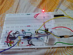
Did this little overcurrent protection circuit last night.

IMG_20151015_102638.jpg

IMG_20151015_102713.jpg

It's quite basic, and self explanatory. It is working fine at 12V DC bus voltage. As soon as I manually connect the wires to get a short circuit, Vgs becomes zero and remains zero till about a second after the SC is removed.

Checked on a scope, Vgs is steady at zero during SC. Vds becomes 12V, indicating that the MOSFET is completely turned off.

Before scaling up, and testing at higher voltages, just wanted you guys to have a look and ensure that the results are proper and not flukes or false positives.

I also want to go for flip flop for proper and complete shutdown. But which one. RS I presume. Thinking on it. The fact that the output is indeterminate in some cases is scaring me. The setup right now holds Vgs steadily at zero even if I just keep the SC wires connected. It probably re-arms every second or so and shuts down again, I presume but I could not detect it on the DSO. Maybe because it's small but it should be substantial at high voltages. Will be able to see how fast the system reacts and how high the current spike goes before shutdown only when it's tested at proper voltage levels.
 

Hi,
Yes that looks like it might work. Be aware of how long the circuit will take to get the device off, and also remember that you may need to add some extra C across the gate/source or gate/emitter in order to counteract the miller capacitance and any dt/dt you may see on the drain/collector terminal. Normally on bigger devices you would use negative gate voltages to ensure the device stays off when there are strong dv/dt's going on above.

Like I said in my piece about pulse testing you only find out how good a protection scheme is until you actually test it properly.

Any flip flop will do (preferably edge triggered for obvious reasons) but as you say watch for illegal states.
 

Status
Not open for further replies.

Similar threads

Part and Inventory Search

Welcome to EDABoard.com

Sponsor

Back
Top