Continue to Site

Welcome to EDAboard.com

Welcome to our site! EDAboard.com is an international Electronics Discussion Forum focused on EDA software, circuits, schematics, books, theory, papers, asic, pld, 8051, DSP, Network, RF, Analog Design, PCB, Service Manuals... and a whole lot more! To participate you need to register. Registration is free. Click here to register now.

Two boost PFC stages in parallel? Must share current.

Status
Not open for further replies.
T

treez

Guest
Hello,
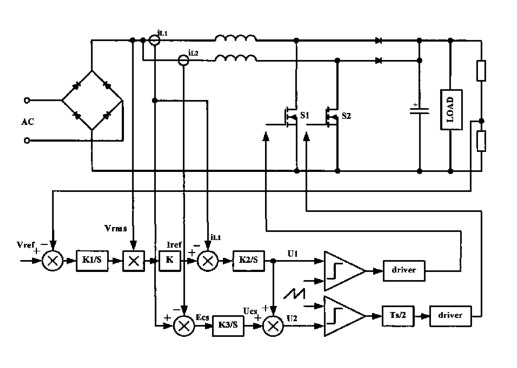
We wish to put two CCM Boost PFC stages in parallel and still ensure they each supply the same current.
We are using LT1248 PFC controller.

LT1248 datasheet
http://cds.linear.com/docs/en/datasheet/1248fd.pdf

In order to ensure that one doesn’t end up supplying all the current, we must bring the voltage error amplifier out of the chip and convert the internal voltage error amplifier into a mere follower by shorting the VAOUT and VSENSE pins.

However, the internal voltage error amplifier has a diode in series with its inverting pin. Does this mean that we can’t connect it as a follower (opamp buffer)?
 

It looks like a mistake on the data sheet, else the op-amp wouldn't work very well if the diode was there, the other option is to override the EA out with another op amp assuming there is limited o/p current on the internal EA, often it is limited to 1mA, easy to test in a mock circuit, set Vea out high and then measure mA out with a multimeter on milli-amps...to gnd.
 
  • Like
Reactions: treez

    T

    Points: 2
    Helpful Answer Positive Rating
It looks like a mistake on the data sheet
I'm pretty certain it's not. LT does this sort of thing all the time, normally the diodes always forward biased so it's the equivalent of just having a fixed DC drop.

So yes, I think it should be possible to force the voltage EA as a buffer.

But I don't think you can use two LT1248 to make an interleaved PFC. They're meant to measure current in the ground return, but the two boost stages need to share the same return path. Every interleaved boost control I've seen uses current sense either on the FET or the inductor.
 
  • Like
Reactions: treez

    T

    Points: 2
    Helpful Answer Positive Rating
A DSP definitely isn't necessary. There are several control ICs which do it, like the UCC28070 and UCC28063. Both need current sensing on the inductor or FET, though.
 
  • Like
Reactions: treez

    T

    Points: 2
    Helpful Answer Positive Rating
A DSP definitely isn't necessary. There are several control ICs which do it, like the UCC28070 and UCC28063. Both need current sensing on the inductor or FET, though.

You probably need separate inductors with current sensing and switches to share for stability or accuracy, but if you can do it differently than measuring average current, then you might be able to avoid copyright infringement, subject to many factors and locations.
7444213700_1438019267.jpg
 

All interleaving schemes are going to require separate boost circuits with their own inductor, FET, and diode, and current sensing. There's no way somebody has a patent on that, hence why controllers are available to implement it. It's to trivial to get an enforceable patent.
 

Just use the EA output of one, buffer it, and use it to force the Ea out of the other... simple so one is a master of sorts and looks at the shunt....

however any slight difference in the power stages and/or the PWM applied to the fets will cause an imbalance, as long as its not too great - you can probably live with it...
 

Status
Not open for further replies.

Similar threads

Part and Inventory Search

Welcome to EDABoard.com

Sponsor

Back
Top