Continue to Site

Welcome to EDAboard.com

Welcome to our site! EDAboard.com is an international Electronics Discussion Forum focused on EDA software, circuits, schematics, books, theory, papers, asic, pld, 8051, DSP, Network, RF, Analog Design, PCB, Service Manuals... and a whole lot more! To participate you need to register. Registration is free. Click here to register now.

500 watt Invert-er Design .

Status
Not open for further replies.

thannara123

Advanced Member level 5
Joined
Jan 7, 2010
Messages
1,580
Helped
122
Reputation
244
Reaction score
114
Trophy points
1,353
Location
India
Activity points
10,387
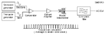
I am planning to make 500 watt sin wave invert-er .?
May i get any good reference to start ?
What are the basic consideration for the invert-er ?
 

You do not want to use an inefficient linear audio amplifier that uses 800W from the battery to make an output of 500W so that it makes 300W of heat. Instead you want an efficient Pulse-Width-Modulation circuit where it has Mosfets turning completely on and completely off so that little battery power is wasted by making heat. The PWM can be at a high enough frequency that a small transformer with a ferrite core can be used.

The inverter circuit should regulate the output voltage so that it does not drop when it is loaded.
 
. The PWM can be at a high enough frequency that a small transformer with a ferrite core can be used.

The inverter circuit should regulate the output voltage so that it does not drop when it is loaded.

Can i get more details
 

Can i get more details
1) Design a 50Hz sinewave oscillator. It will be used to modulate the PWM.
2) Design a high frequency oscillator. it will be the carrier frequency of the PWM.
3) Design the PWM circuit probably using an integrator and comparator.
4) Decide if you want to make the PWM at low voltage but very high current then step up the voltage with a small ferrite core high frequency transformer or use a switched mode power supply to step up the battery voltage then use PWM of the high voltage.
5) Design the voltage regulation circuit.
6) Design an overload shutdown and low battery shutdown circuit.
 
4) Decide if you want to make the PWM at low voltage but very high current then step up the voltage with a small ferrite core high frequency transformer or use a switched mode power supply to step up the battery voltage then use PWM of the high voltage.

I didn't understand ? Sir Are you talking about a transformer less inverter Desgin ?
 

A switched-mode power supply makes a square-wave at the input of a transformer then the transformer steps up the voltage. The output is rectified and filtered into DC. If the square-wave frequency is high then the transformer can be small with a ferrite core.
 
But i need 230 volt Ac output ? with 50 Hz .
 

thannara123 , first of all you have to tell the intended output waveform of the inverter , you are saying that it should be 50Hz AC , AC is more generic word , which includes waveforms like sqaure wave , modified sinusoidal or sinusoidal wave etc.

Are you looking for "modified sine wave inverter" or "sine wave inverter".
and do you want to make a linear bulky transformer based design or SMPS based inverter design ?

If this is your first design , i strongly recommend to start with Transformer based design because it is easy to implement and you will get the basics of the inverter and after successfully designing this inverter , you can move to SMPS based one .

Try searching SG3525 based inverter , you'll get a loads of results.


Regards
 
I want to make an inverter having pure sinwave output (230 AC 50 Hz) .
what is the diffrence between "modified sine wave inverter" or "sine wave inverter ?
I have made lot of invert r circuit with transformer .
i am planning to transformer less one .


.*****************..

I searched the forum and got some concepts ., and i concluded that as follows
1) An H-Bridge :- Used to Convert 12 volt Dc to 340 Volt DC . This is achieving by a high frequency transformer .
2) Second H-Bridge :- Used to convert 340 volt Dc to 230 volt ac by using SPWM .
3) Filter:- To remove the high frequency contents.

Is it correct ?
 

yes you are almost correct. As I saw your requirement is 500W so use PUSH-PULL topology in DC-DC converter stage instead of H-Bridge, This will reduce your cost ,
H bridge is good for inverter rating > 1000VA

and in second stage , you are correct , just chop the DC voltage into SPWM using H-Bridge.
 
can i get any reference circuits for the first stage ?
 

Will you use a 12V battery to power the inverter?
How will you step up the voltage from 12V to a little more than the peak-to-peak voltage of 650V (more than 54 times higher) of the 230VAC sine wave without using a transformer?
Do you know what Pulse-Width-Modulation (PWM) does and how it creates the output sine wave without wasting a lot of battery power making heat?

- - - Updated - - -

Please do not send me a personal message. I live on the other side of the world from you so when you are awake then I am sleeping.
"
thannara123 said:
Sir , may i get a block diagram of an pure sune wave inverter ?
"

I simply looked in Google for it, why didn't you look for it?
 

Attachments

  • sine wave inverter block diagram.png
    sine wave inverter block diagram.png
    6.2 KB · Views: 141

Will you use a 12V battery to power the inverter?
How will you step up the voltage from 12V to a little more than the peak-to-peak voltage of 650V (more than 54 times higher) of the 230VAC sine wave without using a transformer?
Do you know what Pulse-Width-Modulation (PWM) does and how it creates the output sine wave without wasting a lot of battery power making heat?

1) Yes i will use my 12 volt battery for my inverter .
2) My 12 volt will steup-up using DC to Dc converter ( By using push-pull topology ) Capture.JPG
3) In PWM - the 50Hz singal modulated by a high frequency carrier (carrier frequency controls in accordance with feed back monitoring section)
Scope AM.png
4) I think the avoiding of transformer the heat generating in transformer due to eddy current etc will be eliminate And
the size of the whole parts will be reduce ?

thanks may I get a reference or tutorial for it
 

1) Yes i will use my 12 volt battery for my inverter .
2) My 12 volt will steup-up using DC to Dc converter ( By using push-pull topology )
Your block diagram shows a transformer that you do not want.

3) In PWM - the 50Hz singal modulated by a high frequency carrier (carrier frequency controls in accordance with feed back monitoring section)
No. You show AM modulation, not PWM.

4) I think the avoiding of transformer the heat generating in transformer due to eddy current etc will be eliminate And
the size of the whole parts will be reduce ?
The transformer steps up the voltage and its center-tap allows a push-pull driver. Since the transformer is driven by high frequency PWM then the transformer is small with a ferrite core.

- - - Updated - - -

It seems that you do not look in Google to see things like the diagram of what you want or the graph of the PWM pulses that form the low frequency sine wave like this:
 

Attachments

  • pulse width modulation.png
    pulse width modulation.png
    95.2 KB · Views: 180

Yes , i was wronged :bang: in that am modulation . Thanks for the guides
 

Is there any switching Ic(pack) having push pull topology /
 

SG3525
SG3524
TL494

all these are easily available and cheap also.
 

I meant the IC pack is that both(for push-pull topology ) switching MOSFET packed having in single ic package ? to drive from SG3525
 

I suggest you to start with Push-Pull Topology using ICs like SG3525 and SG3524.

Follow this steps to generate a modified Sine wave inverter using SG3525

1) Pin1 and Pin2 are Non-inverting and Inverting pins. It determines the Duty cycle of your PWM. Simply connect Pin1 to the output of your Feedback sense output via transformer and Rectifier with voltage divider. Simply connect Pin2 via Resistor 10k to Pin16(internal reference Voltage of 5.1v)
Pin 3 and Pin4 not used

Pin5,Pin6 and Pin7 determines your Desired PWM Frequency. That's why I have generated a Software which I called the SG3525 calculator. To calculate this manually then use this Formular

F = 1/ Ct(0.7*Rt + 3*Rd)

Where Ct is the timing capacitor at Pin5 to ground
Rt is the timing resistor at pin6 to ground
Rd is the resistor at Pin7 to Pin5

For 50Hz output inverter Pwm generator use
Ct as 0.1u
Rt as 142k
Rd as 100R

Pin8 determines the soft-start, use 10u capacitor from pin8 via ground.
Pin9 is used for compensation, connect 0.1u and 100k in parrallel from pin9 to Pin1
Pin10 is the shutdown pin connect 10k resistor form pin10 to ground
Pin11 and Pin14 are the Output signals Pins to Gates of mosfets via Pull down resistor. Remember that SG3525 have internal mosfet Drivers.
Pin15 and Pin13 must be connected to output of a voltage regulator of 9-12v
Now you get a PWM of 50hz

For more explanation visit www.Pulsetronics.blogspot.com.
 

Status
Not open for further replies.

Part and Inventory Search

Welcome to EDABoard.com

Sponsor

Back
Top