Continue to Site

Welcome to EDAboard.com

Welcome to our site! EDAboard.com is an international Electronics Discussion Forum focused on EDA software, circuits, schematics, books, theory, papers, asic, pld, 8051, DSP, Network, RF, Analog Design, PCB, Service Manuals... and a whole lot more! To participate you need to register. Registration is free. Click here to register now.

[SOLVED] How does COLLET work in APC-7mm Connector?

Status
Not open for further replies.

redcrystalline

Advanced Member level 4
Joined
Nov 10, 2010
Messages
117
Helped
13
Reputation
26
Reaction score
13
Trophy points
1,298
Activity points
1,882
Hi
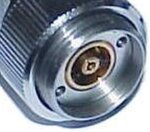
im wondering How does COLLET work in APC-7mm Connector?
i mean does in go inside when connector has been mated?
im so interested to see collet picture individually.
any note or reference or picture about collet functionality is welcomed
thakns
 

I'm also a bit puzzled how the APC7 works. Looking at the diagram SunnySkyguy posted, the collet can protrude 0.010" in front of the reference plane. So if two connectors are mated with the collets protruding 0.010", it would appear the collets would damage each other as the two outer conductors are pressed against each other.

Since the connectors should be gaged with the collets removed, this 0.020" can't be made up by compression of the collet. So what stops them damaging each other?

Dave
 

Obviously the APC-x center connctor is spring loaded.
 

Obviously the APC-x center connctor is spring loaded.

But where is the spring? Certainly depressing a centre conductor there is no obvious sign of a spring, but maybe the movement is too small for me to feel.

Dave
 

The connector specified mating torque and protrusion limit of 10 thou or 254 um must guarantee a tight fit for best Return Loss but no damage from stress.
 

The connector specified mating torque and protrusion limit of 10 thou or 254 um must guarantee a tight fit for best Return Loss but no damage from stress.

But how comes a protrusion of 0.010" is acceptable? On N and 3.5 mm connectors no protrusion is allowed at all. I find good quality (i.e. VNA calibration standard) 3.5 mm and N connectors have the centre pins recessed about 0.0005" behind the reference plane.

Clearly on APC7, if both centre conductors were recessed, there would never be any electrical contact, but I don't know what stops damaged if they are not?

Although I am not a mechanical engineer, if someone asked me to look at the connector and work out how it was designed, I would say the centre conductor would be recessed, the collet precessed a little, but flexible, then when they mate, the collect flexes a bit. But that can't be how it works, as the centre conductor, with the collet removed, should be very close to the reference plane.

Sorry, I am still confused.

Dave
 

Certainly depressing a centre conductor there is no obvious sign of a spring, but maybe the movement is too small for me to feel.
Respectively you're unable to compress it with your fingers.

Review the Rosenberger RPC-7 drawing to understand how the spring effect is achieved.

The term collet gives already a hint how it works.
 

The BeCu material is very elastic used for both outer ring and inner collet which is split to compress during mate contact.
APC7.jpg
The 6 split collet design is more expensive than the cheaper 4 split design attached.


Material
Coupling Mechanism Stainless steel
Body Gold-plated beryllium copper
Center Contacts Gold-plated beryllium copper
Dielectric Support Air-polyphenelene oxide composite
Clamping Components Nickel-plated brass
Crimp Ferrule Nickel-plated copper
 

Attachments

  • APC7a.jpg
    APC7a.jpg
    273.5 KB · Views: 107

coloured3.jpggage-and-connector-without-collet.jpgclose-up-of-important-bits.jpg
The comments here made me look at this in more detail. I attach 3 photos I took - sorry I did't have a flash gun or tripod handy, so they are hand-held. There is also a picture of an APC7 connector gage - this is part of an HP 85050B calibration kit.

To gage the connector, I remove the collet (green device). That exposes the inner conductor (drawn in yellow, does't show up too well).

The outer conductor (marked in red) is not flush with the stainless steel body (shown blue) when the parts are detached. Instead it sits above the stainless steel body.

Looking at this, there's nothing to make the two outer conductors (shown red) actually be flush with the stainless steel body (shown blue). I always assumed the outer conductor was flush with the body, but when one looks carefully, it is not.

So it looks like when they are tightened, both the inner and outer conductors get compressed, but the inner more so, as that might need to move as much as 0.030" more than the outer.

Actually, when I measured the connector with the collet in place, it protruded about 0.003", so nothing like the permitted 0.010 inch.

Dave
 
The link to the APC-7 interface drawing somehow disappedared in post #2.

I think it's obvious that the collect protrusion dimension refers to the uncompressed case. Fully compressed, the collet slides into the tubular inncer connector.
 

So you are saying that almost 100% of the collet goes inside the inner conductor? I assumed the collet may have compress a bit, but the centre conductor moved back.

If both centre pins were recessed 0.0005" from the reference plane, then only a total of 0.001" of gap would exist between them, so the collets would be virtually all inside the inner conductor.

Dave
 

I assume, both inner and outer conductor can be considered rigid and uncompressible in a first order. That's also necessary to provide the stable reference plane specified for APC-7. Only the collet is compressed radially while sliding along it's conical shape into the inner conductor.
 

I assume, both inner and outer conductor can be considered rigid and uncompressible in a first order. That's also necessary to provide the stable reference plane specified for APC-7. Only the collet is compressed radially while sliding along it's conical shape into the inner conductor.

If that's the case, there must be a fairly significant gap between the two stainless steel faces when mated properly. The outer conductor sits a fair bit proud of the stainless steel. I have not measured it, but one can see it in the photos I posted earlier.

It's a shame APC7 are not as cheap as PL259 - I could be tempted to cut one open!

Dave
 

The high performance of this connector which was improved by HP after Amphenol, is due to the precision radius ratios and central position error. It is also desirable for high transmitter powers to have a very low loss contact resistance of the centre conductor. The protrusion spec of 0.010" is a maximum and although no minimum is given, I suspect 0.003 is near the minimum and may have been a result of over-torque.

These are designed to finger tight, unlike F connectors.

I estimate the ratio tolerance of inner surface of OD and outer surface of ID is designed to be <<0.1% for better than 30 dB RL and repeatable to <<0.001% for calibration loads.

The purpose of the collets is to provide a compression interface while maintaining a rigid the outer edge of the inner conductor, because the slightest bulge would affect the Return Loss.
 

These are designed to finger tight, unlike F connectors.

What makes you say they should be finger tight? I have had two HP VNA calibration kits (85050C TRL kit I sold, and an 85050B standard kit I still have). Both have included 12 lb inch torque wrenches for tightening APC7 connectors - the same as N connectors, and a lot more than 3.5 mm or SMA.

12 lb inch is a bit tighter than I can achieve by hand easily, but clearly they are not like 7-16 connectors.

I really like the sexless design of the APC7 - it is a shame that the 3.5 mm connector is not a scaled version of it.

Dave
 

Status
Not open for further replies.

Part and Inventory Search

Welcome to EDABoard.com

Sponsor

Back
Top