Continue to Site

Welcome to EDAboard.com

Welcome to our site! EDAboard.com is an international Electronics Discussion Forum focused on EDA software, circuits, schematics, books, theory, papers, asic, pld, 8051, DSP, Network, RF, Analog Design, PCB, Service Manuals... and a whole lot more! To participate you need to register. Registration is free. Click here to register now.

MC34063 Simulation-0v at pin 5

Status
Not open for further replies.

adeel.sid

Advanced Member level 4
Joined
Feb 15, 2008
Messages
108
Helped
2
Reputation
4
Reaction score
1
Trophy points
1,298
Activity points
1,958
Hello

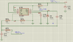
In a project, I have to test working of MC34063, my calculation shows that I will get 5.75V at output (pin 2 right?) that indirectly connected to pin 5.
I checked that voltage varies b/w 9-10 (at N38) and current also fluctuates.

I have attached image of proteus simulation file as reference

Can anyone guide?

Regards
 

Attachments

  • 34063pb.png
    34063pb.png
    45.8 KB · Views: 93

There are dots along the circuit that means you certainly had not connected correctly some components, and this could explain the fluctuating voltage due to some unconnected net. Once it is a simple schematic, I suggest you redraw all of them.
 

There are dots along the circuit that means you certainly had not connected correctly some components, and this could explain the fluctuating voltage due to some unconnected net. Once it is a simple schematic, I suggest you redraw all of them.

I tried to reconnect, but dots appears whenever there are more than one path. For confirmation, I checked voltage after dots to be sure about continuity. All works same

- - - Updated - - -

The pin 2 goes to 5 with inductor not with capacitor.

exploring output since both are energy storage device.

- - - Updated - - -

Problem is 0v (up to 3 decimal point) on pin 5
 

.........................
exploring output since both are energy storage device.
......................
The are both energy storage devices but that certainly doesn't mean you can substitute one for the other. :???: One stores energy with voltage/charge, the other stores energy in the current flow.
 

Right!
I tried to replace it with inductor of value calculated through given link. But no good result:(
 

"no good results" means that is not working as expected, or even not working ?
 

"no good results" means that is not working as expected, or even not working ?

when i place probe, i got some values (almost zero and changing continuously)

- - - Updated - - -

This cannot possibly work with only a tiny cap on the emitter (SWE) and no inductor.

As posted above, i tried it by replacing cap with inductor but cant get expected result (5.75V at 2)
By the way, I'm right when I say out at pin 2 or it should be at other pin?
I'm using this IC first time and confused
 

By the way, I'm right when I say out at pin 2 or it should be at other pin?
I'm using this IC first time and confused.
If you review the datasheet, you see different ways to connect the IC. For a buck converter with internal switch the output is SWE (switch transistor emitter). By nature of the buck converter, there must be a DC path between input and output. So please forget about the silly series capacitor circuit in your original post.

The other question is, why the standard inductor circuit isn't working for you. But this can be hardly guessed without detail informations.
 

Hi,

please show your actual schematic and descirbe the results.

Klaus
 

Also might specify the main requirements such as: switching frequency, desired output voltage, and maximum load current.
 

Status
Not open for further replies.

Similar threads

Part and Inventory Search

Welcome to EDABoard.com

Sponsor

Back
Top