KlausST
Advanced Member level 7
Hi,
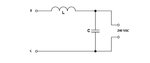
again, please read how LC filter work. I think it is important that you understand what you design. In every description you can see where the input is connected and the output.
Then you will see that the load must be connected to the Cs.
Only change the upper load connection to the upper node of the Cs, so that the load is in parallel to the Cs.
Klaus