Continue to Site

Welcome to EDAboard.com

Welcome to our site! EDAboard.com is an international Electronics Discussion Forum focused on EDA software, circuits, schematics, books, theory, papers, asic, pld, 8051, DSP, Network, RF, Analog Design, PCB, Service Manuals... and a whole lot more! To participate you need to register. Registration is free. Click here to register now.

can microstip board be corrosion?

Status
Not open for further replies.

Tomsin yin

Banned
Joined
Mar 6, 2014
Messages
61
Helped
5
Reputation
10
Reaction score
5
Trophy points
8
Activity points
0
hi guys
currently am designing a power divider with its frequency range 2~3Ghz,and i used a block of microtrip board with its Er=2.65,H=1mm,i had printed the PCB and did the hardware circuit for three blocks,but S11 is very weak,it is only about 10dB(but S11 is more than 20dB in my co-simulation),so i asked my adviser that why my S11 is so lousy,he said nothing but told me not to corrosin microstip board.so i wanna know why microstip board can't be corrosined?could anybody answer me ?
its grateful for ur replys. E7279B3568BA4617E489B63C0B923FF6.jpg
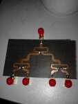
 

How you measured s11, you terminated all other in/outputs with their corresponding impedance? Is the board hand-made? Maybe you have some mismatches in trace width/length? About corrosion, i think it's a minor problem but has some influence, you can remove the oxid with 10% HCl or use some coating. But I think it's more a problem of some mismatches. Did you made some EM-simulation of your structure? What value for s11 you expected? Also remove the excessive solder at the resistors.
 
Last edited:
The connection between your SMA and the microstrip line can be a problem. The long center pin at the input of your divider acts like a thin microstrip line that is cascaded with your circuit. You need to improve the transition = reduce the discontinuity.
 
hi,johnjoe ,thnx a lot
the board is hand-made,i have had EM-simulation in layout window and co-simulation in a new schematic window,both the results r very good,S11 is at least 20dB and other indexs r as well as good.the mismatches u mentioned r considered by me,then i checked my schematic,i think the circuit matched.i think the Er probably changed when board is corrosioning.

- - - Updated - - -

hi,volker,
thnx for ur advice,so can u tell me how to improve the transition ,namely,reduce the discontinuity?
 

so can u tell me how to improve the transition ,namely,reduce the discontinuity?

What you measure is not just the filter. Your measurement includes the connectors, the transition from connector to the PCB and the filter. On the PCB you have 50 Ohm lines, but between the connector (the coax part) and the beginning of the microstrip line you have a long metal pin (the center conductor of the connector) that does not have 50 Ohm. You need to create a better (more controlled) transition from the connector to the 50 ohm line. Minimize the length where you don't have 50 Ohm. Cut the length of the coax center pin, and move the connector closer to the beginning of the 50 Ohm line.

(And forget about that corrosion idea .. your problem is something else)
 
yes that is way too much solder. Try smaller chip resistors and way less solder. Make sure the ground on the coax connectors is intimately soldered to the back side.

How do the other parameters simulated match to the measured? For instance, what about isolation?

One thing you can do is take a wood Q tip, cut off the cotton end, and put a small piece of copper tape at the end. Move it around on your circuit and find where holding it makes the performance better. At that point, solder on a small square of copper. THen if you find a place where holding the copper sick against the circuit makes things worse, cut away with an Xacto knife that portion of the trace. In this way you can TUNE it.

Also, if you have a network analyzer with time domain capability, maybe you can see where the major reflections are coming from
 
It looks like the input trace does not reach the margin of the PCB and the central pin of the input connector is attached to the microstrip line after a few milimeters in air. You should keep leads short and the microstrip line should reach the PCB margin.

Why the outputs of the upper Wilkinson splitter change width when going to the the lower splitters ?

For wide bandwidths you may need multi section splitters.
 
hi biff44
thnx for ur help,patience and effort.
the isolations measured between output ports are more then 20dB,and the insert loss is 7dB or so.i don't know why my S21 is so poor,the index given is no more than 6.3dB ,i have tuned many times,but i could not do the trick.there is a network analyzer in my laboratory made in China which have not the time domain capability,i have changed right angle connectors as strigth ones.
now i have another question that in my circuit board the 50om lines are optimized ,so the "50ohm lines" are closed to 50ohm,then i wanna know if that can cause a great error?

- - - Updated - - -

hi Eugen_E
thnx a lot for ur help.
the power divider i designed used two sections.
 

I am afraid this home made splitter (Wilkinson based) will not work well, because what I see from the picture, the widths of the microstrip lines are all over the range of dimensions.
You can play with any simulator, and you will find that Wilkinson splitter is not as sensitive to the length of the lines as it is to their impedance.
 

Status
Not open for further replies.

Part and Inventory Search

Welcome to EDABoard.com

Sponsor

Back
Top